Industrial grounding is not simply driving a rod into the soil and assuming everything is protected. It is a system of electrodes, conductors, connections, bars, bonding, fault-current paths, soil conditions, measurement and maintenance. Its purpose is to provide an effective path for fault current and reduce dangerous potential differences within the applicable electrical design and regulatory framework.
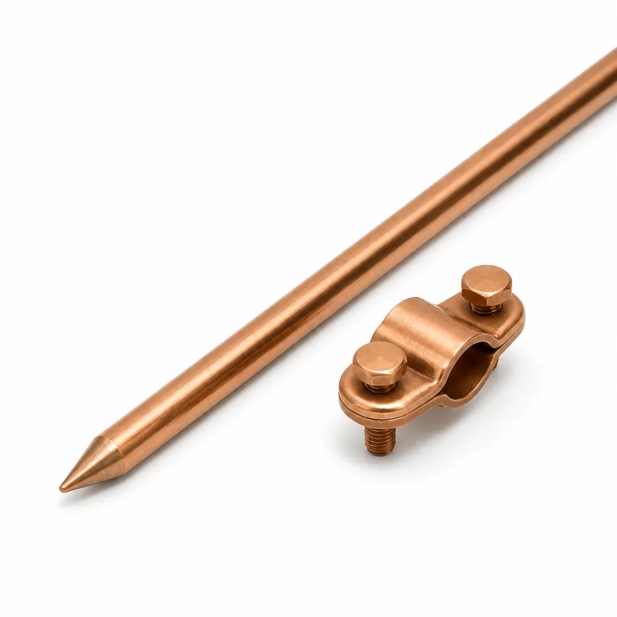
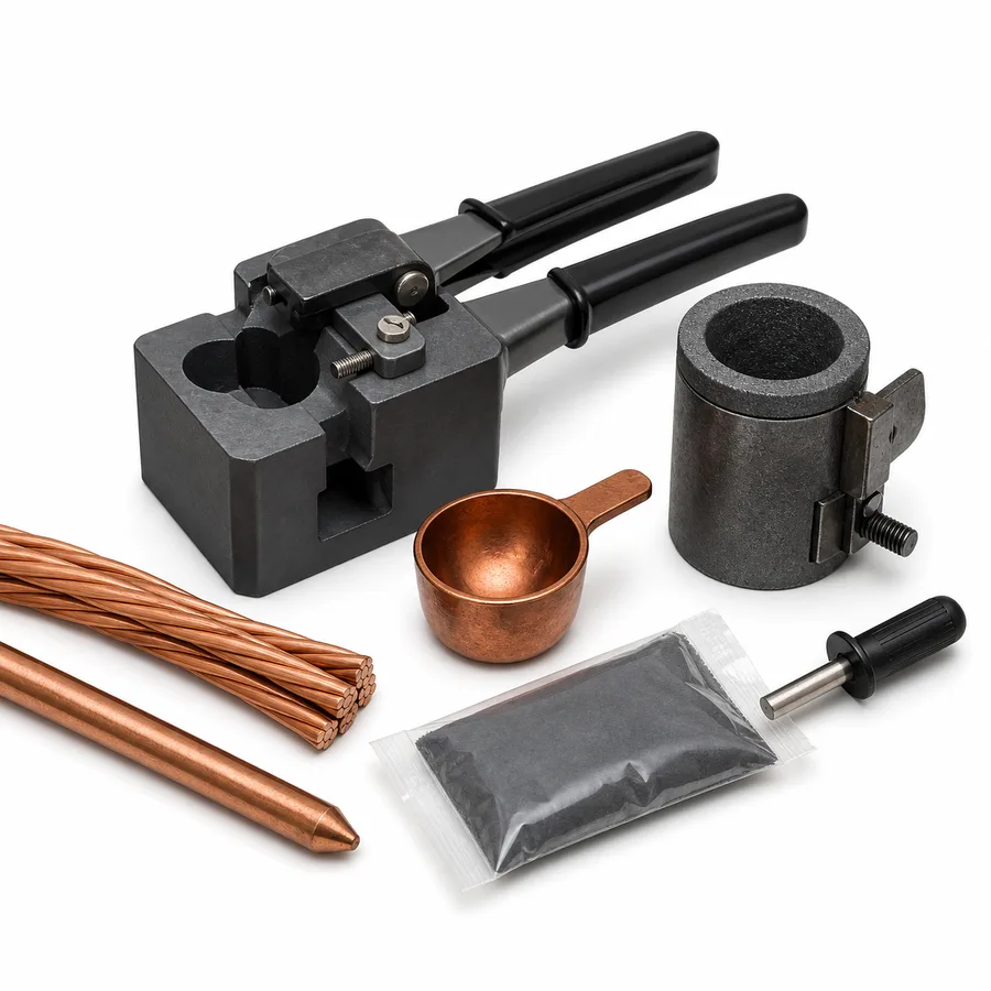
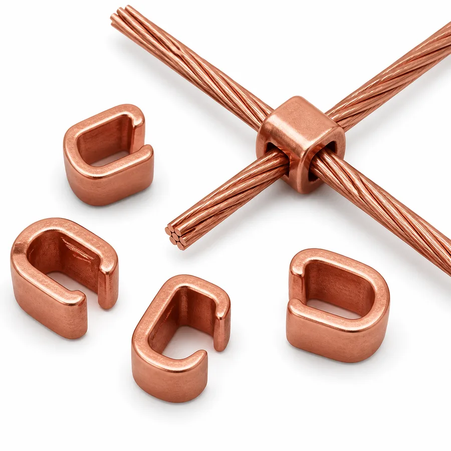
In Colombia, RETIE and NTC 2050 are central references for electrical installations. For safety analysis, soil resistivity measurement and grounding in substations or complex industrial systems, IEEE 80 and IEEE 81 are recognized technical guides. At TECTUL, buyers can start with products such as 5/8 x 2.4 m copper-clad ground rod, exothermic welding and molds, copper compression connector and complete grounding kit.
Grounding performs several functions: potential reference, protective device operation, surge control, equipotential bonding and reduction of touch and step voltages. Not every installation has the same risk. A small panel, a machine, a plant with drives, a lightning protection system and a substation require different criteria. Ground resistance matters, but it is not the only safety indicator.
| Element | Function | Advantage | Selection caution |
|---|---|---|---|
| Copper-clad rod | Vertical electrode in contact with soil | Direct installation and availability | Depends on soil, length, spacing and corrosion |
| Exothermic weld | Molecular connection between conductors and electrodes | Low connection resistance and high durability | Requires correct mold, charge and safe procedure |
| Compression connector | Mechanical joint by controlled deformation | Fast and repeatable with proper tooling | Must match conductor and applicable certification |
| Conductive backfill | Improves electrode-soil contact in some soils | Can stabilize performance in difficult soil | Does not replace design or measurement |
| Measurement | Checks resistivity, continuity and impedance | Supports correction and maintenance decisions | Method must fit site and system |
A copper-clad rod combines a steel core with a copper coating. Steel provides driving stiffness; copper provides surface conductivity and corrosion resistance in many soils. The 5/8 x 2.4 m copper-clad rod is common in industrial, commercial and infrastructure installations, provided the design validates quantity, location, depth and connections. One rod may not be enough in high-resistivity soil, rocky areas, dry seasons or installations with high fault current.
Exothermic welding and molds create a permanent joint between conductors and electrodes. The method is valued because it creates a robust, corrosion-resistant connection with good electrical continuity. The copper compression connector is a mechanical alternative when the correct tool, die and connector are used. The comparison is not “one is always better”: it depends on criticality, environment, inspection, project standard and tool availability.
Conductive cement or ground enhancement material is used to improve contact between electrode and soil in difficult conditions. It may help where natural resistivity is high or changes strongly with moisture. However, it does not turn a poor design into a safe installation. First characterize the site, define the system objective and design the geometry. Then decide whether conductive material adds value.
Grounding measurement requires method. IEEE 81 describes techniques for soil resistivity and ground system impedance measurement. Field methods include Wenner for resistivity and fall-of-potential for resistance or impedance when the site allows enough auxiliary electrode spacing. A ground tester reading should not be interpreted without context: parallel wiring, neutrals, metallic piping, interconnected grids and temporary moisture can influence results.
RETIE establishes safety requirements for electrical installations in Colombia and requires grounding to be integrated with the design and the protection of people, animals and property. NTC 2050 develops installation rules, including grounding and bonding. For technical rigor, avoid promising a universal resistance value as if it applied to every installation. The target depends on voltage, fault current, protective devices, clearing time, use, soil and risk.
For basic industrial grounding, start with design: loads, protection devices, fault current, soil, bonding and applicable rules. Select rods, conductors, exothermic welds or compression connectors as parts of a system, not isolated pieces. Measure resistivity before design when the project requires it and verify continuity and impedance after installation. At TECTUL, provide drawings, conductor size, joint type, environment and inspection criteria to select compatible components.
A grounding system is not evaluated only by the electrode. Bonding between metallic structures, panels, trays, enclosures, piping and protective conductors reduces dangerous potential differences. If equipment is connected to a rod but not to the correct protective system, an unsafe condition or improper protective-device operation may occur. Protective conductor continuity must be verified according to installation and maintenance criteria.
In industrial plants, drives, electronic systems, large motors, lightning protection and communication networks require coordination. Separating grounds without criteria can create potential differences; bonding everything without reviewing fault currents, noise or return paths can also create problems. Design must consider electrical safety, electromagnetic compatibility, surge protection and utility or owner requirements.
Grounding degrades over time. Loose joints, corrosion, civil works, excavations, conductor theft, variable moisture and undocumented expansions change performance. Maintenance should include visual inspection, continuity verification, inspection-pit review, connector condition and comparison of measurements against previous records. A single isolated reading is less useful than a documented trend.
Buried connections need special care because they are not always visible. Exothermic welding reduces loosening points, but it must be performed with the correct mold and charge. Compression connectors can work very well when installed with the proper tool. In both cases, conductor cleaning, size match and final protection affect service life.
Grounding installation may look like a simple civil task, but it involves electrical, mechanical and excavation risks. Before driving rods, buried interferences, existing networks, soil moisture and proximity to energized equipment should be reviewed. In exothermic welding, heat, projection, mold, charge, cleaning and personal protective equipment are controlled. In compression connectors, tool, die and conductor position are controlled.
It is also important to document what remains buried. As-built drawings, photos of connections before backfilling, inspection pit locations and measurement records simplify future maintenance. Without documentation, an expansion can cut conductors or duplicate electrodes without coordination. In audited plants, evidence of correct installation is almost as important as the material purchased.
A complete grounding kit is useful when the application is well delimited and components are compatible. Even then, the kit does not eliminate design. Conductor size, conductor length, connector type, rod dimension, inspection pit, bar, identification and installation tooling must be checked. For repetitive installations, standardized kits reduce mistakes; for critical installations, the kit must match drawings and calculations.
Grounding materials should therefore be bought with the same discipline used for pressure or structural components. The rod, conductor, connector and inspection accessory must match the design, the installation method and the maintenance plan. Substituting one item because it looks similar can change durability, inspection access or electrical continuity.
This is especially relevant after plant expansions, where new equipment is connected to an older grounding network whose condition may no longer match the original drawings.