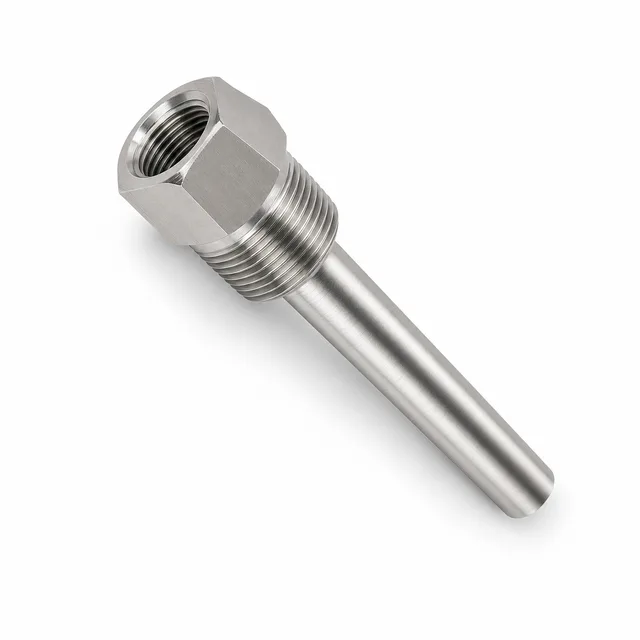
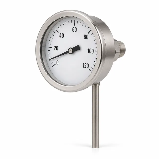
A thermowell is a metal sheath, closed at its tip and threaded, flanged or welded to the pipe or tank, that isolates the temperature sensor (thermocouple, RTD or bimetal thermometer) from the process fluid. Its key function: it allows the sensor to be removed, calibrated or replaced without depressurizing or draining the line, while protecting the element against pressure, fluid velocity, corrosion and abrasion.
Quick verdict: for general water, air and steam services use a threaded NPT thermowell; for corrosive fluids, frequently serviced lines or high pressure classes use a flanged one; for maximum mechanical integrity at high pressure and temperature use a welded design (socket weld or weld-in). If the fluid demands an expensive alloy, the Van Stone design combines an alloy stem with a carbon steel lap-joint flange. In every case, if flow velocity is high, require the wake frequency verification per ASME PTC 19.3 TW-2016.
Every bar-stock thermowell has four elements: the process connection (thread, flange or weld end), the shank with its insertion length U (the portion inside the fluid), the internal bore that receives the sensor, and the instrument connection, normally a 1/2 in NPT female thread.
The industry-standard bore is 0.260 in (6.6 mm) in diameter, sized for 1/4 in (6.35 mm) sensors; for 3/8 in sensors a 0.385 in (9.8 mm) bore is used. The ~0.25 mm diametral clearance is deliberate: enough to insert and extract the sensor, and small enough not to penalize thermal response.
The commercial designation summarizes the three dimensions: a 1/2 × 1/2 × 4 thermowell has a 1/2 in NPT process connection, a 1/2 in NPT instrument connection and a 4 in (101.6 mm) insertion length. This is the format of the TECTUL product pages: stainless thermowell 1/2 × 1/2 × 2.5 in, stainless thermowell 1/2 × 1/2 × 4 in and stainless thermowell 1/2 × 1/2 × 6 in.
| Type | Typical connection | When to use it | Limitation |
|---|---|---|---|
| Threaded | 1/2, 3/4 or 1 in NPT (ASME B1.20.1) | General services: water, air, oils, steam. The most economical and removable | The thread concentrates stress and corrosion; not recommended for severe cyclic services |
| Flanged | Integral flange per ASME B16.5, classes 150 to 2500, raised face (RF) | Corrosive or toxic fluids, tanks and reactors, frequently dismantled lines, high pressure classes | Higher cost; requires a mating flange and gasket on the line |
| Socket weld | Welded into a socket-type coupling | High integrity with no exposed threads; small-bore refinery and steam lines | Removal requires cutting the weld |
| Weld-in | Welded directly to the pipe or elbow | Maximum mechanical strength at high pressure and temperature | Permanent installation; requires a qualified welding procedure |
| Van Stone | Forged collar on the stem, clamped by a loose lap-joint flange | Fluids that demand costly alloys: only the stem is alloy, the loose flange is carbon steel. Classes 150 to 2500 | Fewer standard combinations; quoted per specification |
The shank geometry sets the balance between mechanical strength, natural frequency and sensor response speed.
| Form | Geometry | Thermal response | When to use it |
|---|---|---|---|
| Straight | Constant diameter along the full insertion | Slowest (largest tip mass) | Services with abrasion or general corrosion; short insertions |
| Tapered | Diameter decreasing continuously toward the tip | Intermediate | High flow velocity: it concentrates stiffness at the root and removes mass at the tip, raising the natural frequency; it is the form that most often passes the ASME PTC 19.3 TW calculation |
| Stepped | Typical 3/4 in (19 mm) root stepping down to a 1/2 in (12.7 mm) tip | Fastest (lowest thermal mass at the tip) | When control-loop response time matters and fluid velocity is moderate |
General rule: the thermowell must be at least as corrosion-resistant as the pipe it is installed in, because its wall is thinner than the pipe wall.
| Material | UNS | Typical fluids | Criterion |
|---|---|---|---|
| 304 stainless | S30400 | Water, air, clean steam, oils | General service without significant chlorides |
| 316/316L stainless | S31600 / S31603 | Chemicals, food and pharma, water with moderate chlorides | Molybdenum (2.00-3.00 % per ASTM A276) improves chloride and pitting resistance; it is the standard of the TECTUL catalog |
| Monel 400 | N04400 | Seawater, hydrofluoric acid, deaerated sulfuric acid, caustic solutions | Nickel-copper alloy; avoid in oxidizing acids such as nitric |
| Inconel 600 | N06600 | Furnaces, combustion gases, high-temperature processes | Nickel-chromium alloy with oxidation resistance up to ≈1,175 °C (2,150 °F) per the alloy data sheet |
For extreme chemical services (wet chlorine, hot acids with chlorides), nickel-molybdenum-chromium alloys of the Hastelloy C-276 type are specified; they are quoted per project.
ASME PTC 19.3 TW-2016, Thermowells — Performance Test Code, is the ASME code that establishes how to calculate the stresses and frequencies of a bar-stock thermowell (straight, tapered or stepped) before installing it. It is not paperwork: thermowells fail by fatigue when the frequency at which the fluid sheds vortices matches the natural frequency of the shank.
The physics is that of von Kármán vortices: as the fluid passes around the shank, alternating vortices are shed at a frequency proportional to velocity and inverse to the tip diameter, with a Strouhal number close to 0.22 for industrial flows. Those vortices excite the shank in two directions: transverse to the flow and in line with the flow; the in-line excitation occurs at twice the transverse frequency, so in-line resonance appears at half the velocity of the transverse one.
The central criterion of the code: the ratio between the vortex-shedding frequency and the natural frequency of the installed thermowell must satisfy r ≤ 0.4 in the general case (to also dodge in-line resonance); in low-density gases, operation up to r ≤ 0.8 is admitted if the code's own cyclic stress evaluation supports it. The code also checks static bending stress, allowable external pressure and the stress at the thread or weld section.
The precedent that motivated the TW edition is well known in the industry: in 1995, at the Monju nuclear plant (Japan), a thermowell with a geometry outside the scope of the 1974 code failed by in-line resonance — a mode that edition did not cover — and caused a leak of the sodium coolant. The 2010 and 2016 TW editions incorporated that failure mode into the mandatory calculation.
When to demand the calculation report: steam and gases at high velocity, liquids above the usual design velocity, long insertion lengths, services with pulsation (compressor and pump discharge) and any line where a thermowell failure would release a hazardous fluid.
To quote a thermowell, send: fluid and concentration, operating and design pressure and temperature, fluid velocity if known, type and size of the connection available on the line, insertion length U, and the diameter and type of the sensor it will protect. TECTUL stocks stainless steel thermowells with 2.5 in, 4 in and 6 in insertion, along with the instruments that pair with them: a 3 in bimetal thermometer and a 5 in bimetal thermometer with 1/2 in NPT connection. Flanged, welded, Van Stone and special-alloy thermowells are quoted on request via WhatsApp with the data of the installation point.