 TECTULby IMR
Grooved system flange adapters — compatibility sheet: they mate only with Class 125/150 drilling, never Class 300
TECTUL · Dispatch across Colombia · Exports to Central & South America
Ductile iron flange adapters that solve in a single part the transition from a grooved system to flanged equipment: on one side they take the pipe groove per AWWA C606 and on the other they present a face with ANSI flange drilling. The TECTUL catalog publishes two references —grooved weld neck flange and grooved flat flange— from 1-1/2″ to 6″. This sheet is a compatibility sheet, not a calculation sheet, because the two decisions that make an order fail are about compatibility and not about strength: the adapter mates only with Class 125 or 150 drilling —never with a Class 300 valve or equipment— and its working pressure is set by the manufacturer's style, with a published industry range of 225 to 400 psi depending on brand, not by the AWWA C606 standard. The two data that can be tabulated precisely —the grooved pipe outside diameter by NPS and the Class 150 counter-flange bolt pattern— are in section 1.
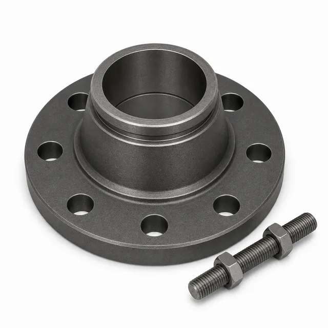
IMPORTANT: reference data — may differ from the physical product; verify with an advisor before buying.
SKU VT-86909 (grooved weld neck flange) · 2 references: weld neck (1-1/2″–4″) and flat (2″–6″) · sold by the unit
1. Technical specifications and compatibility table
What it is and what it solves
A grooved flange adapter is a transition part: at one end it has the geometry of the grooved system —it mounts over the groove machined into the pipe, with its gasket and coupling— and at the other it presents a flanged face with ANSI drilling to bolt to a valve, a pump, a strainer or a tank. Its value is in assembly: it lets you move from a grooved network, which is built without welding and comes apart in minutes, to a piece of equipment that only exists in a flanged version, without welding a flange to the pipe or cutting the line.
And its risk is compatibility. The grooved family has its own dimensional universe —the groove, the pipe's real outside diameter, the coupling style— and the flanged family has its own —the class, the bolt circle, the drilling—. The adapter sits on the border and that is why there are two ways to get it wrong that stay invisible until the part is on site: buying it for drilling other than the one it carries, and assuming a working pressure it does not declare. Both are in section 2.
Compatibility table by size
These are the two data that can be tabulated with standard precision: the steel pipe outside diameter over which the grooved side mounts, and the Class 150 counter-flange bolt pattern the flanged side mates with.
| NPS (DN) | Steel pipe outside dia. | Bolted joint studs (qty × dia.) | Class 150 bolt circle dia. | Holes (qty × dia.) | Catalog reference |
|---|---|---|---|---|---|
| 1-1/2″ (DN 40) | 48.3 mm (1.900″) | 4 × 1/2″ | 98.4 mm (3.88″) | 4 × 15.7 mm (0.62″) | Grooved weld neck flange only |
| 2″ (DN 50) | 60.3 mm (2.375″) | 4 × 5/8″ | 120.7 mm (4.75″) | 4 × 19.1 mm (0.75″) | Both references |
| 2-1/2″ (DN 65) | 73.0 mm (2.875″) | 4 × 5/8″ | 139.7 mm (5.50″) | 4 × 19.1 mm (0.75″) | Both references |
| 3″ (DN 80) | 88.9 mm (3.500″) | 4 × 5/8″ | 152.4 mm (6.00″) | 4 × 19.1 mm (0.75″) | Both references |
| 4″ (DN 100) | 114.3 mm (4.500″) | 8 × 5/8″ | 190.5 mm (7.50″) | 8 × 19.1 mm (0.75″) | Both references |
| 6″ (DN 150) | 168.3 mm (6.625″) | 8 × 3/4″ | 241.3 mm (9.50″) | 8 × 22.4 mm (0.88″) | Grooved flat flange only |
IMPORTANT
This technical data sheet is a reference guide to the properties of this product type; it is not a quality certificate for the product you are buying. The measurements, dimensions and physical or geometric characteristics of the product supplied may vary by manufacturer, heat and lot, and may even fall outside the cited standards. If any of these figures is critical to your design or build, verify it with one of our advisors against the physical product or the lot's mill certificate, so you can be fully certain of what you are buying. · Original data sheet: tectul.com/en/conduccion-de-fluidos/bridas-y-esparragos/ficha-tecnica-brida-con-cuello-ranurada-2.html
The pipe outside diameter is that of steel pipe per ASME B36.10M and does not change with schedule: that is why the grooved side is specified by NPS and groove type, not by schedule. The bolt pattern, circle and drilling are those of the ASME B16.5 Class 150 flange, identical to those of the counter-flange it bolts to (data sheet FT-TC-BRI-AC-001). What is not in this table —and is not published in the catalog— are the adapter body dimensions (length, thickness, neck height) and its bolting thread type: these belong to the manufacturer's style and are confirmed on quotation.
Groove dimensions are not in this sheet
The groove belongs to the pipe, not to the adapter: it is a geometry machined into the pipe (rolled or cut) whose dimensions —width, depth, distance from the end and tolerances— are set by AWWA C606 and published, within this series, by data sheet FT-TC-ACC-RAN-001 on grooved fittings. They are not repeated here. What must be declared when ordering is which groove type the installed pipe has —roll groove or cut groove— because they are not interchangeable and the gasket and coupling are chosen against that figure.
Material: ductile iron ASTM A536 grade 65-45-12
| Property | Minimum value | What it means |
|---|---|---|
| Minimum tensile strength | 448 MPa (65 ksi) | The "65" in the designation: 65,000 psi |
| Minimum yield strength | 310 MPa (45 ksi) | The "45" in the designation: 45,000 psi |
| Minimum elongation | 12 % | The "12" in the designation: 12 % in 50 mm |
| Microstructure | Nodular graphite in a ferritic matrix with some pearlite | This is what separates ductile iron from grey iron: graphite in nodules, not in flakes |
IMPORTANT: reference data — may differ from the physical product; verify with an advisor before buying.
A ductile iron designation is its data sheet: the three numbers in "65-45-12" are, in that order, the minimum tensile in thousands of psi, the minimum yield in thousands of psi and the minimum elongation in per cent. It is the most used A536 grade in pipe fittings and the same one the grooved fittings family uses (data sheet FT-TC-ACC-RAN-001). The deciding figure is the 12 % elongation: that is what makes this material deform before breaking, unlike grey cast iron, which is brittle and not admitted in pressure components of this kind. The catalog does not declare the material of these two references: the real grade is confirmed on quotation.
The catalog's 2 references
| Reference | Flanged side | Published sizes | Characteristic use |
|---|---|---|---|
| Grooved weld neck flange (SKU VT-86909) | Face with ANSI Class 125/150 drilling and a neck | 1-1/2″ · 2″ · 2-1/2″ · 3″ · 4″ (5 variants) | Transition where the neck is needed to align or to gain usable length |
| Grooved flat flange | Flat face with ANSI Class 125/150 drilling | 2″ · 2-1/2″ · 3″ · 4″ · 6″ (5 variants) | Direct transition against the face of a butterfly valve, a strainer or a pump |
IMPORTANT: reference data — may differ from the physical product; verify with an advisor before buying.
The two references cover different ranges: only the weld neck reaches 1-1/2″ and only the flat reaches 6″. Between 2″ and 4″ both are available and the choice is one of assembly, not of strength — see section 3.
General specifications
| Product | Grooved system flange adapter: transition part between a grooved network and flanged equipment, in two configurations (weld neck and flat) |
| Material | Ductile iron ASTM A536 grade 65-45-12 (tensile 448 MPa / 65 ksi, yield 310 MPa / 45 ksi, elongation 12 %). Real grade per reference: confirmed on quotation |
| Grooved side | Grooved joint system per ANSI/AWWA C606, Grooved and Shouldered Joints (current edition C606-22, published 1 April 2023). Pipe groove type —rolled or cut— to be declared when ordering |
| Flanged side | ANSI Class 125 or 150 drilling exclusively: bolt circle, hole count and hole diameter of the ASME B16.5 Class 150 flange. It does not mate with Class 300 or higher classes — see section 2 |
| Working pressure | That of the manufacturer's style, not of the standard. The range published in industry style sheets runs from 225 to 400 psi (15.5 to 27.6 bar) by brand and size: confirmed on quotation against the supplied style's sheet |
| Catalog range | 1-1/2″ to 4″ (DN 40 to DN 100) in the weld neck reference; 2″ to 6″ (DN 50 to DN 150) in the flat one |
| Dominant application | Fire protection networks and service water lines, where the grooved system is the assembly standard. UL/FM certification of the supplied style: confirmed on quotation |
| Gasket | That of the grooved coupling style, not a flange gasket: defined by the style manufacturer together with fluid and temperature. Not included |
| Sale | By the unit, per reference and size |
| Applicable standards | ANSI/AWWA C606-22 (grooved and shouldered joints) · ASTM A536 (ductile iron, grade 65-45-12) · ASME B16.5 (Class 150 counter-flange drilling) · ASME B36.10M (steel pipe outside diameter) · ASME PCC-1-2022 (bolted joint tightening). Internal reference for the groove: data sheet FT-TC-ACC-RAN-001 |
2. Compatibility sheet: the four data and the three warnings
The four data that define the order
This sheet carries no calculation section because the adapter is not sized: it is matched. The four data you must have before ordering, in order of how many orders each one ruins:
| # | Datum | Why it decides | Where to get it |
|---|---|---|---|
| 1 | Class of the flanged equipment on the other side | The adapter mates only with Class 125 or 150 drilling. If the equipment is Class 300, the adapter will NOT do: neither the bolt circle nor the hole count match | Marking on the valve, pump or equipment; its data sheet |
| 2 | Real outside diameter of the grooved pipe | The grooved side mounts over the pipe outside diameter. On steel pipe by NPS that value is standardized (section 1 table), but there is imported pipe with metric diameters that do NOT match any NPS | Direct measurement of the installed pipe, with tape or caliper |
| 3 | Pipe groove type | Roll groove and cut groove are not interchangeable, and the gasket and coupling depend on which it is | Pipe inspection; the site's grooving procedure |
| 4 | Adapter style and working pressure | The rating belongs to the manufacturer's style and varies almost twofold between brands: 225 to 400 psi per the style sheet | Style sheet of the supplied adapter's manufacturer |
Warning 1: it mates only with Class 125/150 — never with Class 300
This is the incompatibility no Spanish-language sheet underlines and the one that sends back the most material. A grooved flange adapter is made with the drilling of the ANSI Class 125 (cast iron) or Class 150 (steel) flange, which share a bolt pattern, and with no other. Against a Class 300 valve, pump or strainer there is no way to bolt it, and the reason is geometric, not one of strength:
| Size | Class 150: bolt circle and holes | Class 300: bolt circle and holes | Do they match? |
|---|---|---|---|
| 2″ | 120.7 mm · 4 holes of 19.1 mm | 127.0 mm · 8 holes of 19.1 mm | No: different circle and twice the holes |
| 3″ | 152.4 mm · 4 holes of 19.1 mm | 168.3 mm · 8 holes of 22.4 mm | No: different circle, different dia. and twice the holes |
| 4″ | 190.5 mm · 8 holes of 19.1 mm | 200.0 mm · 8 holes of 22.4 mm | No: different circle and different hole dia. |
| 6″ | 241.3 mm · 8 holes of 22.4 mm | 269.9 mm · 12 holes of 22.4 mm | No: different circle and 12 holes against 8 |
IMPORTANT: reference data — may differ from the physical product; verify with an advisor before buying.
From 2″ up the hole count already differs between the two classes, so the mistake is discovered when the part is presented. Between 1/2″ and 1-1/4″ both classes have 4 holes and only the bolt circle changes by a few millimetres: there the mistake is more treacherous, because it "almost fits". If the equipment on the other side is Class 300, the answer is not to force the grooved adapter: it is to install a Class 300 flange welded or threaded to the pipe (data sheet FT-TC-BRI-AC-001) and give up the grooved joint at that point.
Warning 2: the working pressure belongs to the style, not to the standard
AWWA C606 standardizes the geometry of the grooved joint —groove dimensions, tolerances, joint requirements— but it does not assign a working pressure to a flange adapter. That number is declared by the manufacturer for its specific style, and the range found published in industry style sheets runs from 225 to 400 psi (15.5 to 27.6 bar) by brand and size: a spread of nearly twofold between the low and the high end.
The design consequence is direct: you cannot specify "grooved flange adapter, AWWA C606" and take a pressure for granted. You must specify the style or require the rating in writing. And the purchasing consequence too: two adapters of the same size that look identical may have ratings 175 psi apart. That is why in this sheet the supplied product's working pressure is declared as a figure to confirm on quotation, not published as our own.
Warning 3: imported units may carry metric bolting
A purchasing detail that appears on no data sheet and does appear on site: imported "grooved type" adapters are published with metric bolting —M16, M20, M24— instead of the ASME B16.5 inch series. An M16 bolt is not a 5/8″ and an M20 is not a 3/4″: they are different diameters, with different threads and different nuts. If the joint is assembled with the bolting supplied with the adapter there is no problem; the problem appears when a bolt is lost and replaced with whatever is in the store, or when the bolting is quoted separately against the inch stud table. Check the thread of the supplied adapter before quoting its bolting.
3. Weld neck or flat, fire protection and assembly order
Weld neck or flat: the choice is one of assembly
| Criterion | Grooved weld neck flange | Grooved flat flange |
|---|---|---|
| Catalog sizes | 1-1/2″ · 2″ · 2-1/2″ · 3″ · 4″ | 2″ · 2-1/2″ · 3″ · 4″ · 6″ |
| Single exclusive size | 1-1/2″ (the flat one does not have it) | 6″ (the weld neck does not have it) |
| Flanged face | With a neck: gains usable length and eases alignment | Flat: bears directly against the equipment face |
| Characteristic use | When the equipment must be spaced from the grooved coupling or alignment corrected | Direct transition against a butterfly valve, strainer or pump |
| Drilling | ANSI Class 125/150 | ANSI Class 125/150 |
| Material | Ductile iron ASTM A536 (grade to be confirmed) | Ductile iron ASTM A536 (grade to be confirmed) |
Neither withstands more pressure than the other because of its shape: the rating is set by the manufacturer's style, the same in both. The choice is made by available space, by alignment and by the size needed — and at 1-1/2″ and 6″ there is no choice, because there is only one reference.
Why this part lives in fire protection networks
The grooved system is the assembly standard for fire protection networks for a practical reason: a sprinkler network is long, branched and installed in false ceilings and tight spaces, and a grooved joint is built without welding, without sparks, without a hot work permit, and comes apart for maintenance in minutes. In that context the flange adapter is the part that connects the network to whatever is flanged: the OS&Y gate valve, the indicating butterfly valve, the strainer, the fire pump and its header.
Hence the requirement to verify in this market: in fire protection, components are usually required with UL listing or FM approval of the supplied style. That certification belongs to the manufacturer's style, just like the pressure rating, and cannot be inferred from AWWA C606: it is requested in writing. The TECTUL catalog's fire protection family groups the remaining components of that line.
The assembly mistake characteristic of this part
It is a sequencing mistake, not a selection one: tightening the bolted joint before the grooved coupling is fully seated. The grooved side has assembly clearance by design —that is what gives the joint its angular flexibility— and if the flange is tightened first, that clearance is taken up unevenly and the coupling gasket ends up loaded to one side. The correct order is the reverse: first seat and tighten the grooved coupling to its style's torque, then bolt the flange in a star pattern in passes (ASME PCC-1-2022). And one check that saves a disassembly: verify that the adapter's flanged face is parallel to the equipment's before inserting the first stud.
4. Frequently asked questions
Will a grooved flange adapter do for a Class 300 valve?
No. The adapter is made with the drilling of the ANSI Class 125 or 150 flange and with no other, and against a Class 300 neither the bolt circle nor the hole count match. At 3″, for instance, Class 150 has 4 holes of 19.1 mm on a 152.4 mm circle and Class 300 has 8 holes of 22.4 mm on a 168.3 mm circle: there is no way to bolt them together. If the equipment on the other side is Class 300, you must give up the grooved joint at that point and install a Class 300 flange welded or threaded to the pipe.
How much pressure does a grooved flange adapter withstand?
Whatever the manufacturer's style declares, and that is the complete answer: AWWA C606 standardizes the geometry of the grooved joint but assigns no working pressure to this part. The range published in industry style sheets runs from 225 to 400 psi (15.5 to 27.6 bar) by brand and size — nearly twofold from one end to the other. Two adapters of the same size that look identical may differ by 175 psi, so the supplied product's rating is requested in writing and confirmed on quotation.
What do I need to know before ordering one?
Four data: (1) the class of the flanged equipment on the other side —if it is 300, the adapter will not do—; (2) the real outside diameter of the grooved pipe, measured, because there is imported pipe with metric diameters that match no NPS; (3) the groove type of the pipe, rolled or cut, which are not interchangeable; and (4) the adapter's style and rating. With those four the order will not fail; without the first, the part gets returned.
What is the difference between the grooved weld neck flange and the flat one?
The neck and the size range, not the strength. The weld neck gains usable length and eases alignment correction; the flat bears directly against the equipment face and is the typical transition to a butterfly valve, a strainer or a pump. Both carry ANSI Class 125/150 drilling and both are ductile iron, so their rating is equally set by the manufacturer's style. In the TECTUL catalog only the weld neck is published in 1-1/2″ and only the flat reaches 6″: at those two sizes there is no choice.
Where are the groove dimensions?
In data sheet FT-TC-ACC-RAN-001 on grooved fittings, and they are not repeated here because the groove belongs to the pipe, not to the adapter: it is a geometry machined into the pipe (width, depth, distance from the end and tolerances) set by ANSI/AWWA C606. What must be declared when ordering the adapter is the groove type: roll groove or cut groove.
Is the adapter's bolting in inches?
Not necessarily. Imported adapters are frequently published with metric bolting —M16, M20, M24— instead of the ASME B16.5 inch series, and an M16 is not a 5/8″ nor an M20 a 3/4″: diameter, thread and nut all differ. As long as the bolting supplied with the part is used there is no problem; the problem appears when replacing a bolt with whatever is in the store or when quoting the bolting separately against the inch stud table in data sheet FT-TC-BRI-ESP-001. Check the thread of the supplied adapter.
Why is it used so much in fire protection networks?
Because the grooved system is the assembly standard for those networks: it is built without welding, without sparks, without a hot work permit, and comes apart for maintenance in minutes, which in false ceilings and tight spaces decides the project. The flange adapter is the part that connects that network to components that only exist flanged: the OS&Y gate valve, the indicating butterfly valve, the strainer and the pump. In that market UL listing or FM approval of the supplied style is usually also required, which cannot be inferred from AWWA C606 and is requested in writing.
Is the flange or the grooved coupling tightened first?
The grooved coupling first, to its style's torque, and the flange afterwards in a star pattern in passes. The grooved side has assembly clearance by design —that is what gives the joint its angular flexibility—: if the flange is tightened first, that clearance is taken up unevenly and the coupling gasket ends up loaded to one side. And before inserting the first stud, check that the adapter's flanged face has ended up parallel to the equipment's.
5. Application notes
Feasibility
The grooved flange adapter is the correct transition when there is a grooved network on one side and Class 125 or 150 flanged equipment on the other: fire protection networks, service water lines, pump headers, strainers and indicating valves. It is not viable in three cases, and in all three the alternative is the conventional flange in data sheet FT-TC-BRI-AC-001: when the equipment on the other side is Class 300 or higher (a geometric incompatibility, not one of strength); when the design pressure exceeds the supplied style's rating; and when the specification demands a joint with no ductile iron parts or with material traceability the style does not offer. Nor is it the right part if the pipe is not grooved: grooving pipe on site is prior work with its own procedure and tolerances, tabulated in data sheet FT-TC-ACC-RAN-001.
Installation
Seat and tighten the grooved coupling first to its style's torque, and only then bolt the flange: the grooved side has assembly clearance by design and tightening the flange first takes it up unevenly, leaving the coupling gasket loaded to one side. Before inserting the first stud, check that the adapter's flanged face is parallel to the equipment's; forcing parallelism with the bolting is the most common cause of leakage in a bolted joint. Tighten in a star pattern in passes and close with a circular pass (ASME PCC-1-2022). Use bolting matching the adapter's real thread —which on imported parts may be metric— and do not infer it from the inch table. Check the pipe's real outside diameter with a caliper before assembly: that is the fit governing the grooved side.
Design
Do not specify this component as "grooved flange adapter per AWWA C606" and take a pressure for granted: the standard sets the geometry of the grooved joint, not the adapter's rating, and the range published in the industry runs from 225 to 400 psi depending on the manufacturer's style — nearly twofold between ends. Specify the style or require the rating in writing. Check on the drawing the class of every flanged item the grooved network will connect to: a single Class 300 component in the line invalidates the adapter at that point and it must be solved with a conventional flange. If the project is fire protection, UL listing or FM approval belong to the supplied style and are requested in writing: they cannot be inferred from the standard. Final selection of style, material, rating and assembly procedure is the responsibility of the line designer per the project code (NFPA 13, the applicable NTC, ASME B31 or other) and its current edition.
6. Technical notice and limitation of liability
This sheet is a compatibility sheet and expressly declares what it does NOT publish: the adapter's working pressure and its body dimensions. The reason is that no standard sets either: they belong to the manufacturer's style, and the rating range found published in industry style sheets runs from 225 to 400 psi (15.5 to 27.6 bar) by brand and size. That range is cited as evidence of market dispersion, not as the supplied product's rating, which is confirmed on quotation against the style sheet.
The two data that are published with standard precision are the steel pipe outside diameter by NPS (ASME B36.10M, invariant with schedule) and the Class 150 counter-flange bolt pattern (ASME B16.5). The Class 150 against Class 300 comparison in section 2 uses that same standard's tabulated values and demonstrates a geometric incompatibility: it is not a strength warning. Groove dimensions are not in this sheet: they belong to the pipe, are set by ANSI/AWWA C606 and this series publishes them in data sheet FT-TC-ACC-RAN-001.
The material is declared as ASTM A536 grade 65-45-12 ductile iron, being the ordinary grade for this family of parts; the catalog does not declare the material of these two references and the real grade is confirmed on quotation with the supplier's certificate. UL listing or FM approval, when a fire protection project requires them, belong to the manufacturer's style and cannot be inferred from AWWA C606. Final selection of style, material, rating and assembly procedure is the responsibility of the line designer per the project code and its current edition.
Sources
- ANSI/AWWA C606 — Grooved and Shouldered Joints (edición vigente C606-22, publicada el 1 de abril de 2023, que reemplaza a C606-15 y añade requisitos de permeación y de apoyo de empuje): normaliza la geometría de la unión ranurada y de hombro para tubería de hierro dúctil y tubería metálica de presión de diámetro IPS, sus accesorios y componentes para servicio de agua. NO asigna presión de trabajo a un adaptador de brida: ese rating es del estilo del fabricante
- ASTM A536 — Standard Specification for Ductile Iron Castings: grado 65-45-12, con tracción mínima de 448 MPa (65 000 psi), fluencia mínima de 310 MPa (45 000 psi) y alargamiento mínimo de 12 %, en condición de fundido, con microestructura de grafito nodular en matriz de ferrita con algo de perlita
- ASME B16.5-2025 — Pipe Flanges and Flanged Fittings: NPS 1/2 Through NPS 24 Metric/Inch Standard (edición vigente, obligatoria desde el 1-ene-2026): patrón de pernos, diámetro del círculo de pernos y barrenado de la brida clase 150 con la que empata el lado bridado del adaptador, y los de la clase 300 usados en la comparación de incompatibilidad de la sección 2 — clase 150: 120,7 mm y 4 agujeros de 19,1 mm en 2″; 152,4 mm y 4 de 19,1 mm en 3″; 190,5 mm y 8 de 19,1 mm en 4″; 241,3 mm y 8 de 22,4 mm en 6″. Clase 300: 127,0 mm y 8 de 19,1 mm en 2″; 168,3 mm y 8 de 22,4 mm en 3″; 200,0 mm y 8 de 22,4 mm en 4″; 269,9 mm y 12 de 22,4 mm en 6″
- ASME B36.10M — Welded and Seamless Wrought Steel Pipe: diámetro exterior del tubo de acero por diámetro nominal, invariante con la cédula — 48,3 mm en 1-1/2″; 60,3 mm en 2″; 73,0 mm en 2-1/2″; 88,9 mm en 3″; 114,3 mm en 4″; 168,3 mm en 6″. Es el diámetro sobre el que se monta el lado ranurado
- Fichas de estilo de fabricantes de sistema ranurado y de importadores del sector (consultadas jul-2026 en la investigación de mercado de esta serie): los ratings publicados para adaptadores de brida ranurados de 1-1/2″ a 12″ se distribuyen entre 225 y 400 psi según marca, estilo y diámetro, y todas coinciden en que el adaptador empata únicamente con taladrado ANSI clase 125 o 150 (o su equivalente PN 10/16) y nunca con clase 300. Varias fichas de importación publican tornillería métrica M16, M20 y M24 en lugar de la serie en pulgadas
- ASME PCC-1-2022 — Guidelines for Pressure Boundary Bolted Flange Joint Assembly (secuencia de apriete en estrella por pasadas y pasada circular de cierre de la unión bridada del adaptador)
- Ficha técnica TECTUL FT-TC-ACC-RAN-001 — Accesorios ranurados: dimensiones de la ranura, tipos laminada y cortada, tolerancias y explicación del grado 65-45-12 del hierro dúctil (datos que esta ficha enlaza y no repite)
- Ficha técnica TECTUL FT-TC-BRI-AC-001 — Bridas de acero al carbón forjado ASTM A105, clases 150, 300 y 600: tabla dimensional y de taladrado de la contrabrida, y alternativa cuando el equipo del otro lado es clase 300
- Ficha técnica TECTUL FT-TC-BRI-ESP-001 — Espárragos y tornillería de brida: cantidad, diámetro, longitud y par de apriete de la unión bridada en la serie en pulgadas
- Catálogo TECTUL, familia bridas y espárragos (consultado 05-ago-2026): referencias «Brida Con Cuello Ranurada» (SKU VT-86909, 1-1/2″ a 4″, 5 variantes) y «Brida Plana Ranurada» (2″ a 6″, 5 variantes), ninguna de las dos con material declarado
This data sheet is the property of TECTUL, part of the Industrias IMR group. Reproduction without attribution is prohibited. Original document and updates: tectul.com/en/conduccion-de-fluidos/bridas-y-esparragos/ficha-tecnica-brida-con-cuello-ranurada-2.html.