 TECTULby IMR
Ductile iron check valves for pumping stations — flanged non-slam silent check valve and swing check valve
TECTUL · Dispatch across Colombia · Exports to Central & South America
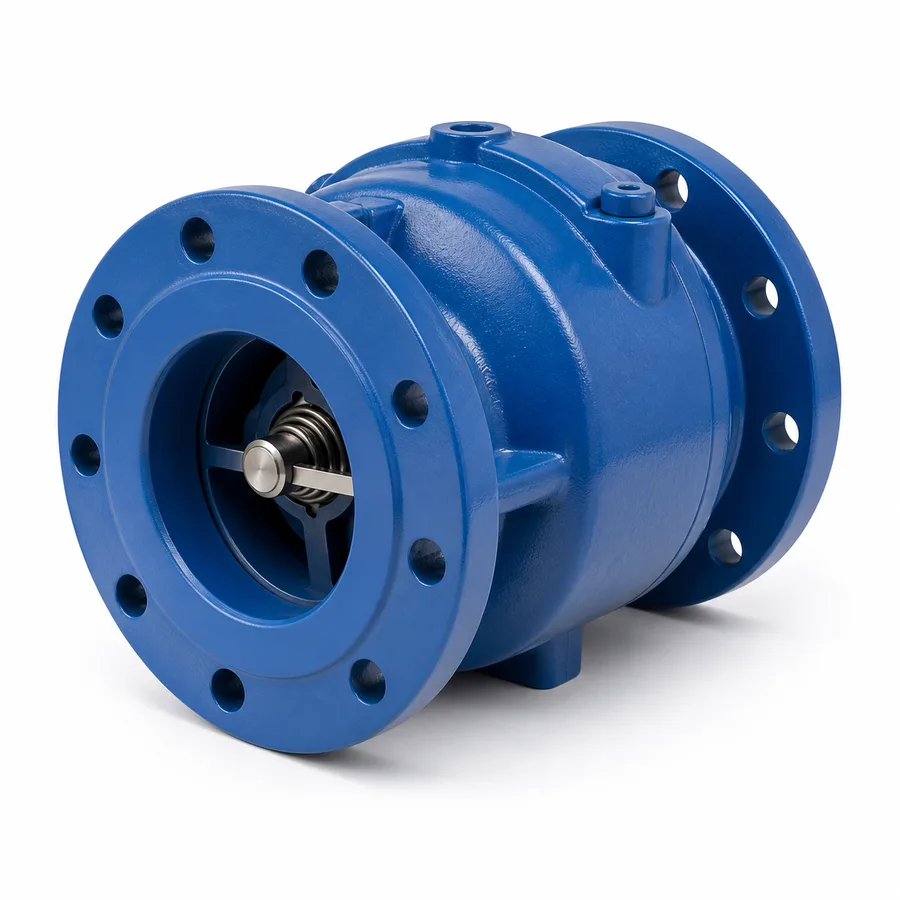
The two flanged ductile iron check valves in the TECTUL catalog for pumping stations: the non-slam check valve, spring-assisted and closing before the flow reverses, and the swing check valve, of classic hinged-disc design with a bolted access cover for waterworks networks and medium-size discharges. The difference between the two is not one of material or rating: it is one of closing speed versus the physics of water hammer. This sheet develops that physics with the Joukowsky equation and a worked numerical example —wave celerity, return velocity and surge pressure—, explains why the slow-closing swing check valve generates the surge that the non-slam design avoids, and publishes face to face and working pressure by size for both references.
Important: Before using these data in engineering, design or installation decisions on systems exposed to mechanical, pressure, rupture, fatigue, impact or water-hammer risk, it is essential to read the technical notice and limitation of liability at the end of this sheet.
SKU VT-cheque-antigolpe-ariete-hierro-ductil (non-slam check valve) · family of 2 flanged ductile iron check valve designs for pumping stations
1. Technical specifications
The two references in the TECTUL catalog
| Reference | Closing mechanism | Characteristic service |
|---|---|---|
| Ductile iron non-slam check valve | Axially guided disc with a spring-assisted closure: the spring pushes the disc toward the seat throughout the whole cycle, not only at the end | Pumping stations with frequent starts and stops, long or high discharge columns, where slow-closing water hammer is a real risk |
| Ductile iron swing check valve | Swing disc hung from an offset pin, gravity closing, with a bolted top access cover | Waterworks networks with relatively steady flow and medium-size pump discharges without frequent abrupt stops |
Materials by component
| Component | Material | Designation / source of the data |
|---|---|---|
| Body and cap | Cast ductile iron | Equivalent to ASTM A536 grade 65-45-12 |
| Disc | Ductile iron or bronze depending on figure, with or without elastomeric coating at the seating edge | Manufacturer data per figure |
| Shaft / disc pin | 400-series stainless steel or bronze, depending on design | Manufacturer data |
| Closing spring (non-slam reference) | 300-series stainless steel | Exact grade: manufacturer data |
| Seat | Bronze ring or elastomeric insert (NBR/EPDM), replaceable, per figure | Manufacturer data |
| External coating | Fusion-bonded epoxy or industrial anti-corrosion paint | Thickness: manufacturer data |
| Ends | Flanged | ASME B16.1, class 125 |
Reference composition of ductile iron per ASTM A536. The exact grade of the disc, spring and seat per figure are manufacturer data for each reference and are confirmed on quotation or in the PDF sheet attached to the product.
Regulatory framework and supply conditions
| Valve type | Check (non-return): operates by itself, driven by the flow; no handwheel or actuator |
| Body material | Cast ductile iron, ASTM A536 |
| Ends | Flanged per ASME B16.1, class 125 |
| Pressure rating | Manufacturer working pressure per size, within class 125; the exact certified value is confirmed on quotation |
| Catalog sizes | Confirmed on quotation per reference |
| Usual fluids | Treated and raw water, at waterworks, irrigation and industrial pumping stations |
⚠ Important: this technical data sheet is a reference guide to the product's properties; it is not a quality certificate for the product you are buying. Heats vary from one another and may differ from the values stated here, or even depart from the standards. If your application requires compliance with a standard, always check the quality certificate (mill certificate) of the lot you are buying. If in doubt, ask one of our technical advisors →
2. The physics of check-valve closing water hammer
What happens when the pump stops
When a station's pump stops —due to a power cut or normal control— the fluid that was moving at operating velocity begins to decelerate. If the discharge column is long or tall, the inertia of that water mass makes it keep moving forward after the pump has stopped pushing, and then reverse, flowing back toward the pump. The check valve must close before that reversal gains significant speed. If the disc reaches the seat late, it seats against a column already moving in the opposite direction, and that abrupt stop of a moving mass produces the transient overpressure known as closing water hammer (slam).
The Joukowsky equation
The magnitude of that overpressure, for a closure that is instantaneous or very fast relative to the pressure wave's travel time in the pipe, is given by the Joukowsky relation:
- Δp: transient overpressure (Pa)
- ρ: fluid density (kg/m³; ≈1,000 kg/m³ for water)
- a: pressure wave celerity in the pipe (m/s) — depends on the fluid's bulk modulus and the pipe's material and wall thickness, not on the valve
- Δv: change in fluid velocity that the closure cancels (m/s)
Worked numerical example
Pumping station with steel piping, a 400 m discharge column, a return velocity at the instant of closure of 1.2 m/s (a slow-closing check valve that lets the column gain speed before sealing) and an estimated wave celerity of 1,000 m/s, a characteristic value for steel pipe with water (the actual celerity depends on diameter, wall thickness and the material's elastic modulus and must be calculated for each line, not assumed).
- Δv = 1.2 m/s (the return velocity cancelled by the closure)
- a = 1,000 m/s (reference wave celerity for steel-water in this geometry)
- ρ = 1,000 kg/m³
- Δp = 1,000 × 1,000 × 1.2 = 1,200,000 Pa ≈ 1.2 MPa ≈ 174 psi
174 psi of transient overpressure, added to the line's normal working pressure, can far exceed class 125 of the check valve and the network's other components. This is exactly the scenario the spring-assisted closure seeks to avoid: if the check valve closes before the flow reaches that return velocity, the effective Δv —and hence Δp— is drastically reduced, potentially to a fraction of the calculated value.
Why a slow check valve causes the surge and an assisted-closing one avoids it
| Swing check valve, gravity closing | The disc only starts to close when forward flow drops enough for its own weight to overcome it. On long columns or frequently stopping pumps, that closure may complete when the return flow already has the example's Δv velocity: the surge appears, with the characteristic sharp bang. |
| Non-slam check valve, spring-assisted | The spring pushes the disc toward the seat throughout the deceleration of forward flow, not only once gravity finally acts: closing completes before the flow reaches reversal, so the Δv that closing cancels is much smaller —ideally close to zero—. |
The wave celerity (a) and the actual return velocity (Δv) of a specific line are not properties of the check valve: they depend on the pipe's diameter, material and wall thickness, the column's length, the pumping set's inertia and the actual operating point. The full transient calculation belongs to the project engineer under the applicable code (ASME B31.1 or B31.3); this section develops the physical principle and an illustrative example, not a certified figure for a specific line.
3. Face to face and working pressure by size
Face to face (F2F)
Flanged ductile iron check valves do not follow a unified face-to-face table equivalent to API 594 or ASME B16.10: each manufacturer sets its own dimensional pattern for the swing or guided-disc body, within the general envelope of a class 125 flanged valve. This sheet does not publish a face-to-face table by size because no single primary standard fixes it for this body type: the exact value per size and figure is confirmed on quotation with the factory PDF sheet.
Working pressure by size
The reference rating of both figures is the manufacturer's working pressure, published within the class 125 flange rating (ASME B16.1), with no primary-standard pressure-temperature table such as ASME B16.34 for steel existing for this body design. As with the rest of the catalog's check valve series, the certified value per size must not be assumed from another reference or another size: it is confirmed on quotation with the factory certificate or PDF sheet.
| Flange class | ASME B16.1, class 125 (cast iron flange pattern) |
| Reference rating | Manufacturer working pressure per size, without hydraulic shock |
| Reference temperature | Cold water service at ambient temperature; for hot water or special services, verify with the manufacturer |
| Face to face | Manufacturer's own pattern, within the flange class envelope — confirmed on quotation |
The absence of a face-to-face table and a primary-standard pressure-temperature table for this body type is not an omission of this sheet: it is a real characteristic of the product category, consistent with the catalog practice of multiple ductile iron waterworks check valve manufacturers.
4. Selection criteria: swing, non-slam or dual-plate wafer
The TECTUL catalog offers three different answers to the same problem —closing off a pump's return flow— and the correct choice depends on the operating profile, not on size:
| Ductile iron swing check valve | Gravity closing, simpler and more economical. Suitable for networks with relatively steady flow, without frequent pump stops or long discharge columns, where the risk of slow-closing water hammer is low. Access cover for disc and seat maintenance. |
| Ductile iron non-slam check valve | Spring-assisted closing, designed specifically for the section 2 scenario: pumping stations with frequent starts and stops, long or tall columns, where a swing check valve would generate a measurable surge. It is the ductile iron answer, larger and heavier, to the same problem the dual-plate wafer check solves in a lighter metallic line. |
| Dual-plate wafer check (separate data sheet) | Same spring-assisted closing logic, but in a short-face-to-face wafer body, mounted between flanges with no ends of its own: the surgical choice where axial space is limited or weight matters. On large waterworks sizes with their own flanged ends, the ductile iron non-slam in this sheet is usually the natural reference. |
Questions that define the choice
- How many times a day does the pump stop and start? Frequent starts favour assisted closing (non-slam or dual-plate) over swing.
- How long or tall is the discharge column? Long columns accumulate more kinetic energy at the moment of stopping: higher risk of surge with slow closing.
- Is the gap between flanges fixed by existing piping? If the retrofit requires short face to face, the dual-plate wafer check enters the comparison even at large sizes.
- Is an access cover required for periodic inspection? The swing check includes it as standard; on the non-slam it is confirmed per figure.
None of these rules replaces the project's hydraulic transient analysis: they are pre-selection criteria. The final decision, especially at critical stations, belongs to the project engineer with the full calculation from section 2 applied to the line's actual data.
5. Frequently asked questions
What water-hammer surge does a slow-closing check valve generate?
It depends on the pipe's wave celerity and the return velocity cancelled at closure: in the section 2 worked example, with a celerity of 1,000 m/s and a Δv of 1.2 m/s, the overpressure is ≈174 psi (1.2 MPa), calculated with Δp = ρ·a·Δv. The actual value for each line depends on its own geometry and must be calculated specifically.
Why doesn't the non-slam check valve generate that surge?
Because the spring pushes the disc toward the seat throughout the deceleration of forward flow, and closing completes before the flow reaches reversal at significant velocity: the Δv that closing cancels is much smaller than that of a swing check valve that closes by gravity alone.
Which ductile iron check valve should I choose for my pumping station?
The non-slam check valve where there are frequent starts and stops or long discharge columns; the swing check valve where flow is relatively steady and surge risk is low. At sizes where the gap between flanges is limited, also compare against the catalog's dual-plate wafer check.
How much pressure do these valves take?
The manufacturer's working pressure per size, within the class 125 flange rating (ASME B16.1). No primary-standard pressure-temperature table equivalent to ASME B16.34 exists for this body type: the exact certified value is confirmed on quotation.
Is there a face-to-face table for these valves?
Not a unified primary-standard table: each manufacturer sets its own pattern within the class 125 flange envelope. The exact value per size and figure is confirmed on quotation with the factory PDF sheet.
6. Application notes
Feasibility
The non-slam check valve covers pumping stations with frequent starts and stops, long or tall columns and a real risk of slow-closing water hammer; the swing check valve covers waterworks networks with relatively steady flow and pump discharges without frequent abrupt stops. Both within the working pressure the manufacturer confirms for each size, class 125 flange rating. Out of scope: sizes or pressures exceeding class 125 (where flanged class 150 steel or higher applies, with its own data sheet) and applications where the project's transient analysis requires a certified overpressure figure beyond the physical principle illustrated in section 2.
Installation
Class 125 mating flanges (ASME B16.1), clean and parallel before mounting the valve; studs of the count and diameter of that class, tightened in a cross pattern and in stages. Check the body's flow-direction arrow against the actual flow. On the swing check valve, the access cover faces up, reachable for maintenance. Leave a straight run upstream, free of elbows and immediate reducers, so the disc does not chatter. Neither figure is installed with downward vertical flow.
Design
Choose between swing and non-slam by the pump's operating profile —starting frequency and discharge column length— not by nominal size. When the preliminary analysis in section 2 suggests significant water-hammer risk, commission the project engineer to run the full transient calculation (actual pipe wave celerity, return velocity at the operating point, certified closing time of the figure) under the applicable code (ASME B31.1 or B31.3), and also consider specific control devices —a surge anticipating relief valve— if the calculation requires it.
7. Technical notice and limitation of liability
The materials framework in this sheet combines ASTM A536 (ductile iron) and ASME B16.1 (class 125 flange) with the data TECTUL publishes on each product page. Neither figure publishes its certified working pressure nor its face to face per size: no unified primary-standard pressure-temperature table or dimensional table exists for this body type; both values are confirmed on quotation with the factory certificate or PDF sheet.
The numerical example in section 2 applies the Joukowsky equation (Δp = ρ·a·Δv) with illustrative wave celerity and return velocity values, to explain the physical principle of closing water hammer. It is not a certified overpressure figure for any actual line: the wave celerity, return velocity and closing time of a specific project must be calculated against its own pipe geometry, pumping set and operating point.
These values must not be used as the sole criterion in critical or safety applications, or wherever valve failure or water hammer may compromise people, property or the environment: in such cases the design and transient analysis belong to the project's responsible engineer under the applicable code. Before deciding with these data, consult our technical team.
Sources
- ASTM A536 — Standard Specification for Ductile Iron Castings, grado de referencia 65-45-12
- ASME B16.1 — Gray Iron Pipe Flanges and Flanged Fittings, clase 125: bridas de acoplamiento de ambas figuras
- Relación de Joukowsky (N. Joukowsky, 1898) — ecuación fundamental de golpe de ariete Δp = ρ·a·Δv, base teórica de la sección 2, consistente con la formulación recogida en manuales de hidráulica transitoria (p. ej. Wylie & Streeter, Fluid Transients in Systems)
- Crane Technical Paper No. 410, Flow of Fluids through Valves, Fittings and Pipe — principio de dimensionamiento de válvulas de retención y comportamiento de cierre
- ASME B31.1 / ASME B31.3 — códigos de tubería de potencia y de proceso: marco al que corresponde el análisis del transitorio hidráulico y de las cargas de tubería
- Práctica general de instalación de válvulas de retención en estaciones de bombeo: cierre por gravedad frente a cierre asistido por resorte, consistente entre múltiples fabricantes
- Curaduría interna TECTUL (data/etapas/etapa-1-conduccion-de-fluidos/curaduria.json) — referencias, agosto 2026
This data sheet is the property of TECTUL, part of the Industrias IMR group. Reproduction without attribution is prohibited. Original document and updates: tectul.com/en/conduccion-de-fluidos/valvulas/ficha-tecnica-cheque-antigolpe-ariete-hierro-ductil.html.