 TECTULby IMR
Free-floating ball check valves — flanged ductile iron for wastewater and threaded bronze for viscous fluids
TECTUL · Dispatch across Colombia · Exports to Central & South America
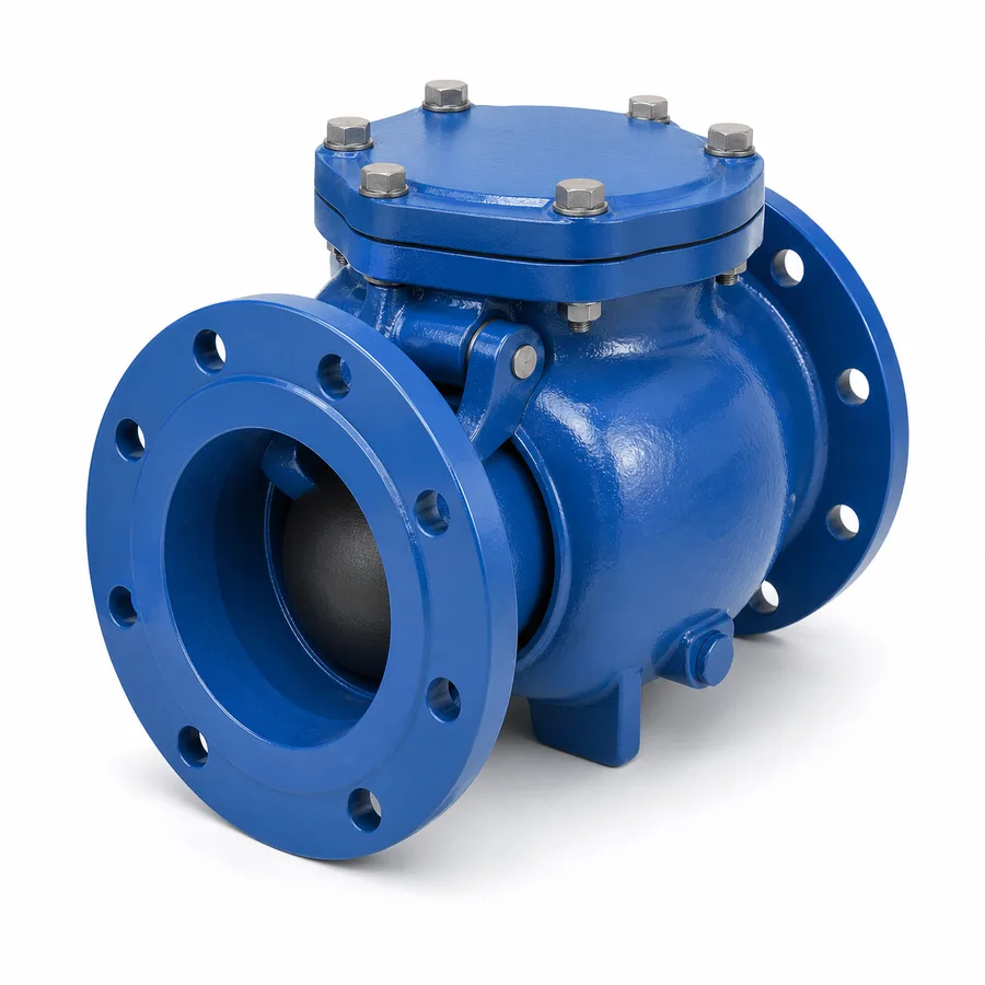
The two free-floating ball check valve versions in the TECTUL catalog: the flanged ductile iron ball check for wastewater networks and sludge pumping, and the threaded bronze ball check for viscous or particle-laden fluids in small pipe. Both share the same principle: an elastomer-coated sphere, lighter than water, pushed by the flow itself out of the bore's axis, with no guides, pins or hinges that solids or fibres can jam. The datum that decides selection on the ductile iron line is not the nominal size but the admissible ball diameter versus the expected solids size in the network; this sheet publishes that relationship, the admissible mounting position of each version and the maintenance of the bolted access cover.
Important: Before using these data in engineering, design or installation decisions on systems exposed to mechanical, pressure, rupture, fatigue, impact or water-hammer risk, it is essential to read the technical notice and limitation of liability at the end of this sheet.
SKU VT-cheque-bola-hierro-ductil (ductile iron ball check) · 2 free-floating ball check valve designs in the TECTUL catalog
1. Technical specifications
The two versions in the TECTUL catalog
| Reference | Body | Ends | Characteristic service |
|---|---|---|---|
| Ductile iron ball check | Cast ductile iron, with a bolted top access cover | Flanged, ASME B16.1 class 125 | Wastewater, sludge and sewage pumping: the ball passes solids that a disc or gate would jam on |
| Bronze ball check | Cast bronze | NPT threaded | Viscous, thick fluids or fluids with fine particles in small sizes, where a narrow-seat disc sticks or clogs |
Materials by component
| Component | Ductile iron | Bronze |
|---|---|---|
| Body | Ductile iron, ASTM A536 grade 65-45-12 equivalent | Cast bronze, ASTM B62 C83600 equivalent (84–86 % Cu, 4–6 % Sn, 4–6 % Pb, 4–6 % Zn) |
| Ball | Solid or sponge rubber core, elastomer-coated (NBR or EPDM depending on fluid), lighter than water | Same principle, smaller core sized to the threaded diameter |
| Seat | Replaceable seat ring, elastomeric or metallic per figure | Integral with the body or replaceable ring, per figure |
| Access cover / plug | Bolted cover on top of the body, with a gasket, for inspection and ball removal without dismantling the line | Threaded plug or bolted cover per figure, smaller size |
| External coating | Fusion-bonded epoxy or industrial anti-corrosion paint, thickness per manufacturer catalog | No coating — bronze is inherently resistant to general water corrosion |
Reference composition of ductile iron per ASTM A536 and of bronze per ASTM B62. The exact ball elastomer grade, seat type and coating thickness per figure are manufacturer data for each reference and are confirmed on quotation.
Regulatory framework and supply conditions
| Valve type | Free-floating ball check (non-return): operates on its own, with no shaft, hinge or actuator |
| Ductile iron body | ASTM A536, flanged ends per ASME B16.1 class 125 |
| Bronze body | ASTM B62, NPT threaded ends per ASME B1.20.1 |
| Reference rating | Manufacturer's working pressure per figure (partial WOG on the ductile iron line; the MSS SP-80 dual-class framework on the threaded bronze line) — confirmed on quotation, see section 2 |
| Catalog sizes | Confirmed on quotation per reference |
| Usual fluids | Wastewater, sludge, activated sludge (ductile iron); molasses, heavy oils, slurries and fine-particle fluids (bronze) |
⚠ Important: this technical data sheet is a reference guide to the product's properties; it is not a quality certificate for the product you are buying. Heats vary from one another and may differ from the values stated here, or even depart from the standards. If your application requires compliance with a standard, always check the quality certificate (mill certificate) of the lot you are buying. If in doubt, ask one of our technical advisors →
2. Admissible ball diameter and the reference rating
The selection criterion is not the DN: it is the free ball diameter
In sewage pumping, the datum that decides whether the check valve works is not the nominal pipe diameter, but the free ball diameter the valve lets through without opening (the so-called solids handling or solids passage). A typical submersible wastewater pump has a declared solids passage —for example 3″ (76 mm)— precisely so it does not clog on rags, wet wipes or coarse solids carried by the municipal network. If the check valve downstream of that pump has a smaller solids passage than the pump, the check valve becomes the obstruction point of the whole system, even if the pipe's nominal diameter is correct.
| Selection rule | The check valve's admissible ball diameter must be equal to or greater than the declared solids passage of the upstream pump, not merely match the pipe DN. |
| Datum to confirm | The exact solids passage per figure and size (in mm or inches) is published by the manufacturer of each reference: confirmed on quotation against the project pump's data sheet. |
| Consequence of omitting the criterion | A disc or swing check valve with a narrow seat on the same network clogs on the same solids the pump was designed to handle: it is the most common selection error in wastewater pumping stations. |
This sheet does not publish the ball diameter per figure and DN because the manufacturer does not declare it uniformly across the whole line: it is confirmed on quotation with the actual solids passage of the project pump as input data.
Reference rating: partial WOG (ductile iron) and dual classes (bronze)
The flanged ductile iron line publishes a manufacturer working pressure (partial WOG-type rating, with no primary-standard pressure-temperature table equivalent to ASME B16.34 existing for this design): the exact value per size is confirmed on quotation. The threaded bronze line is read, like the rest of the catalog's threaded bronze valves, under the MSS SP-80 dual class framework (SWP on saturated steam and WOG cold, linked to the same class): a bronze ball check marked "200 WOG" belongs to Class 125, with a saturated steam limit of 125 psig at ≈178 °C, and the exact class number of this figure is confirmed on quotation, just like the rest of the catalog's bronze check line.
Neither figure in this sheet publishes its class or its certified pressure per size: the value of another threaded bronze reference in the catalog or of a ductile iron disc check from another line must not be assumed.
3. How the free ball works and access cover maintenance
The ball rolls clear of the flow path
Unlike a disc or swing check valve —which always has a mechanical part (pin, hinge, guide) in close contact with the flow— the free ball check valve has no articulated part exposed to the bore. The elastomer-coated sphere, lighter than the liquid, rests on the seat when there is no flow; as forward flow starts, pressure and turbulence push the ball upward and to one side of the chamber, leaving a wide, practically unrestricted path for the fluid and the solids it carries. When flow stops or reverses, the ball falls back onto the seat by its own buoyancy and the push of the return flow.
That geometry is why the free ball check valve does not jam where a disc check valve does: there is no pin or hinge where a fibre, a rag or a root can tangle and block closing; no narrow guide where a solid particle can wedge; and the valve's inner chamber is usually wider than the bore of an equivalent disc valve, precisely to give the ball room to roll.
Maintenance: the access cover
The ductile iron line includes a bolted top cover that allows access to the ball chamber without dismantling the line: remove the cover, inspect or replace the ball and seat, and close it again with its gasket. This is the valve's periodic maintenance point, because the ball's elastomeric coating is the wear item:
- Coating wear. Repeated contact against the seat and abrasion from suspended solids wear the ball's elastomer over time; a worn ball loses tightness and allows reverse leakage at low differential pressure.
- Periodic inspection. Open the access cover during the pumping station's scheduled maintenance to check the condition of the ball and seat, without cutting the line or draining the entire wet well.
- Replacement. The ball and seat ring are individual spare parts: they are replaced without needing to change the whole valve body.
Inspection frequency depends on the fluid's aggressiveness (solids concentration, presence of grease or abrasives) and the pump's starting regime: there is no universal interval and the maintenance plan is set by the plant operator or the manufacturer.
4. Mounting position and head loss
Admissible positions
| Horizontal | Design position for both versions: the ball rests on the seat with the access cover facing up, accessible for maintenance. |
| Vertical, upward flow | Admissible on both versions: the ball falls by gravity onto the seat when flow stops, same as horizontal. |
| Vertical, downward flow | Not admissible: with downward flow gravity pushes the ball in the same direction as the fluid, toward opening, and the valve loses its closing function — the same principle governing any gravity check valve. |
The exact admissible position and the flow direction marked on the body are defined by the manufacturer of each figure: the arrow cast on the body always overrides this table.
Head loss: the wide chamber has a cost
The same wide chamber that gives the ball room to roll clear of the flow introduces a higher head loss than a straight-through disc check valve of the same nominal size: the fluid does not travel in a straight line, it flows around the volume occupied by the displaced ball. In wastewater networks that extra loss is usually an accepted cost in exchange for eliminating clogging risk, but it must be included in the pump's system curve calculation, especially at stations with a long discharge column where the available pressure margin is tight.
The head loss coefficient (Cv or K) per size and figure is manufacturer data and is confirmed on quotation: no generic figure is published because it varies with each manufacturer's chamber design.
Field rules
- Leave vertical access above the bolted cover for maintenance work, with no piping or supports blocking its removal.
- Check the flow direction marked on the body before mounting: as with any check valve, the arrow indicates direction, not mounting position.
- Confirm the admissible ball diameter against the project pump's solids passage before ordering (section 2): it is this family's actual selection criterion.
- The ball check valve is not an isolation valve: to work on the line, an isolation valve is installed upstream.
5. Frequently asked questions
What solids diameter does a ball check valve pass?
It depends on the figure and nominal size: the manufacturer publishes the admissible free ball diameter per reference, and that value is confirmed on quotation against the project pump's declared solids passage. The selection rule is that the check valve's solids passage must equal or exceed that of the upstream pump, not merely match the pipe's nominal diameter.
Why doesn't a ball check valve jam where a disc one does?
Because it has no pin, hinge or narrow guide exposed to the flow: the ball simply rolls clear of the liquid stream when there is forward flow and falls back onto the seat by its own buoyancy. A disc or swing check valve, by contrast, has articulated parts where rags, fibres or coarse solids can tangle and block closing.
Which ball check goes with wastewater and which with viscous fluids?
The flanged ductile iron ball check is the reference for wastewater, sludge and sewage pumping, with an access cover for maintenance. The threaded bronze ball check is used in small sizes for viscous, thick fluids or fluids with fine particles where a narrow-seat disc check sticks or clogs.
In what position is it installed?
Horizontal, with the access cover facing up, or vertical with upward flow. Never vertical with downward flow: the ball relies on gravity to close and downward flow pushes gravity in the opposite direction.
How much pressure does the ductile iron line take?
The manufacturer publishes a reference working pressure per figure that is not certified under a primary-standard pressure-temperature table equivalent to ASME B16.34: the exact value per size is confirmed on quotation.
How often is the ball inspected?
There is no universal interval: it depends on the fluid's aggressiveness and the pump's starting regime. The practical criterion is to open the access cover during the station's scheduled maintenance and inspect wear on the ball's elastomeric coating and the seat.
6. Application notes
Feasibility
The ductile iron ball check covers wastewater, sludge and sewage pumping stations where solids passage is the deciding criterion, within the working pressure the manufacturer confirms for each size. The bronze ball check covers viscous, thick fluids or fluids with fine particles in small sizes, within the MSS SP-80 dual class framework the manufacturer confirms. Out of scope: low-viscosity potable water with no solids, where a conventional disc check valve has lower head loss and lower cost; and any service where the manufacturer does not confirm the admissible ball diameter against the solids passage the project requires.
Installation
Mount horizontally with the access cover reachable facing up, or vertically with upward flow; never vertically with downward flow. Check the body's flow-direction arrow before connecting the line. On the flanged ductile iron line, use the stud count and diameter of the ASME B16.1 class 125 flange and tighten in a cross pattern and in stages. On the threaded bronze line, seal with a sealant compatible with the fluid and tighten by torque, not by turns. Leave clear space above the access cover so it can be removed without dismantling the adjacent pipe.
Design
Select by the admissible ball diameter against the project pump's declared solids passage, not by the pipe's nominal diameter alone. Include in the system curve calculation the extra head loss of the ball check's wide chamber versus a straight-through disc check valve, particularly at stations with a long discharge column. The reference rating of each figure applies to non-shock conditions; water hammer, piping loads and the project's design code (ASME B31.1, B31.3 or the applicable one) are outside the scope of this sheet.
7. Technical notice and limitation of liability
The materials framework in this sheet combines ASTM A536 (ductile iron), ASTM B62 (C83600 bronze), ASME B16.1 (flanges of the ductile iron line) and the reference MSS SP-80 dual class framework for the threaded bronze line, with the data TECTUL publishes on each product page. Neither figure publishes its admissible ball diameter, its pressure class nor its certified pressure per size: those values are confirmed on quotation with the factory certificate or PDF sheet and must not be assumed from another reference.
The head loss cited in section 4 is qualitative: no generic Cv or K coefficient is given because it varies with each manufacturer's chamber design. The mounting position in section 4 applies general gravity check valve installation practice: the arrow cast on the body and the product PDF sheet override this table.
These values must not be used as the sole criterion in critical or safety applications, or wherever valve failure may compromise people, property or the environment: in such cases the design belongs to the project's responsible engineer under the applicable code. Before deciding with these data, consult our technical team.
Sources
- ASTM A536 — Standard Specification for Ductile Iron Castings, grado de referencia 65-45-12
- ASTM B62 — Standard Specification for Composition Bronze or Ounce Metal Castings, aleación C83600
- ASME B16.1 — Gray Iron Pipe Flanges and Flanged Fittings, clase 125: bridas de la línea de hierro dúctil
- ASME B1.20.1 — Pipe Threads, General Purpose, Inch: roscas NPT de la línea de bronce
- MSS SP-80 — Bronze Gate, Globe, Angle and Check Valves: sistema de clases duales SWP/WOG usado como marco de lectura de la línea de bronce roscada
- Práctica general de bombeo de aguas residuales: criterio de paso de sólidos (solids handling) de bombas sumergibles y su compatibilidad con la válvula de retención aguas abajo, consistente entre múltiples fabricantes de equipos de bombeo
- Crane Technical Paper No. 410, Flow of Fluids through Valves, Fittings and Pipe — comportamiento hidráulico general de válvulas de retención
- ASME B31.1 / ASME B31.3 — códigos de tubería de potencia y de proceso: marco de diseño para golpe de ariete y cargas de tubería
- Curaduría interna TECTUL (data/etapas/etapa-1-conduccion-de-fluidos/curaduria.json) — referencias, agosto 2026
This data sheet is the property of TECTUL, part of the Industrias IMR group. Reproduction without attribution is prohibited. Original document and updates: tectul.com/en/conduccion-de-fluidos/valvulas/ficha-tecnica-cheque-bola-hierro-ductil.html.