 TECTULby IMR
Grooved-end check valves for fire protection networks — gate type and damped-piston hydro type, UL/FM listed
TECTUL · Dispatch across Colombia · Exports to Central & South America
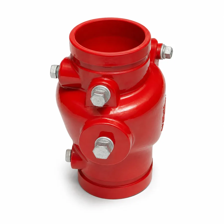
The two grooved-end check valves in the TECTUL catalog: the UL/FM-listed grooved gate-type check valve for fire protection networks, and the grooved hydro-type check valve with a damped piston for building hydropneumatic systems. Both share the same end type —a circumferential groove that receives a rigid or flexible coupling instead of a bolted flange— and the same underlying requirement: on a fire protection network, working pressure, listing and mounting position are not optional data, they are conditions for approval by the authority having jurisdiction. This sheet publishes how the grooved coupling works, the reference UL/FM listings, the functional difference between the gate type and the hydro type, and this family's most commonly violated installation rule: a grooved check valve is not a pipe anchor point.
Important: Before using these data in engineering, design or installation decisions on systems exposed to mechanical, pressure, rupture, fatigue, impact or water-hammer risk, it is essential to read the technical notice and limitation of liability at the end of this sheet.
SKU VT-cheque-compuerta-ranurado (UL/FM grooved gate check) · family of 2 grooved-end check valve designs in the TECTUL catalog
1. Technical specifications
The two references in the TECTUL catalog
| Reference | Closing mechanism | Characteristic service |
|---|---|---|
| UL/FM grooved gate check valve | Gate lifted by the flow, falling back by gravity | Fire protection network: prevents return of water toward the fire pump or the incoming supply, at the point required by NFPA for the pumping station or network inlet |
| Grooved hydro check valve | Piston with a spring and hydraulic damping of the closure | Building hydropneumatic systems (pressure tank, constant-pressure network) and also accepted on fire protection network runs where silent closing is sought |
Materials by component
| Component | Material | Designation / source of the data |
|---|---|---|
| Body | Cast ductile iron | Equivalent to ASTM A536 grade 65-45-12 |
| Gate or piston disc | Ductile iron with an elastomeric sealing coating, or bronze depending on figure | Manufacturer data |
| Spring (hydro reference) | 300-series stainless steel | Exact grade: manufacturer data |
| Hydraulic damper (hydro reference) | Piston with a calibrated orifice that retards final closure, reducing impact | Manufacturer data |
| Ends | Circumferential groove machined per the standard of the project's grooved coupling system | Groove dimension: data from the coupling manufacturer, not from the valve alone |
| External coating | Fire-network red paint or epoxy coating, per project specification | Colour and thickness: project/manufacturer data |
Reference composition of ductile iron per ASTM A536. The exact sealing coating grade, hydraulic damper and groove dimension per figure and size are manufacturer and project coupling-system data: confirmed on quotation.
Regulatory framework and supply conditions
| Valve type | Check (non-return), grooved ends: operates on its own, driven by the flow |
| Body material | Cast ductile iron, ASTM A536 |
| Ends | Grooved, compatible with rigid or flexible couplings of the line's system |
| Reference listings | UL 262 and/or FM 1120 depending on figure and size; the exact certificate is confirmed on quotation |
| Working pressure | 175 psi (12.1 bar) or 300 psi (20.7 bar) depending on coupling and listing, without hydraulic shock — see section 2 |
| Catalog sizes | Confirmed on quotation per reference |
| Usual fluids | Fire protection network water (potable, raw or reserve) and treated water hydropneumatic systems |
⚠ Important: this technical data sheet is a reference guide to the product's properties; it is not a quality certificate for the product you are buying. Heats vary from one another and may differ from the values stated here, or even depart from the standards. If your application requires compliance with a standard, always check the quality certificate (mill certificate) of the lot you are buying. If in doubt, ask one of our technical advisors →
2. How the grooved end works and the UL/FM listings
The coupling carries the axial load; the gasket seals
A flanged end transmits the pipe's axial load (weight, pressure, thermal expansion) through the flange faces and the tightened studs. A grooved end solves the same problem with a different geometry: the pipe carries a circumferential groove machined near each end, and a coupling —two or more metal segments that engage that groove and are bolted together— mechanically holds the two ends and transmits the axial load, while an internal elastomeric gasket seals against fluid pressure. It is a demountable joint, faster to install than a flanged joint and requiring no welding or bevelling, widely used in fire protection networks for installation speed.
Two direct consequences of that geometry:
- The groove belongs to the system, not to the valve alone. The exact groove dimension (axial position, width, depth) is set by the standard of the coupling manufacturer used on the project: the grooved valve must be compatible with that same coupling standard, and that compatibility is confirmed on quotation against the system specification.
- Rigid vs. flexible coupling. A rigid coupling allows no angular movement between the two ends; a flexible one does, within a small range, absorbing some misalignment and thermal expansion. The choice between them is a network design decision, not a fixed property of the valve.
UL/FM listings: what they certify
On fire protection networks, equipment is not specified by pressure and material alone: it must be listed by a recognised laboratory for that specific use. UL 262 (Underwriters Laboratories, gate valves for fire service) and the FM 1120 approval program (FM Approvals, check valves) are the two reference listings the industry requires in North America and that many Colombian projects adopt by insurer specification or reference NFPA code.
| UL 262 | Underwriters Laboratories standard for fire-service gate valves: covers construction, hydrostatic testing, operating cycle and marking. |
| FM 1120 | FM Approvals approval standard for check valves: pressure testing, cycling testing and the specific certification per size and figure. |
| Scope of this sheet | Publishes both listings as the reference framework of the product category; the exact certificate and listing number of each figure and size are issued by the manufacturer and confirmed on quotation, never assumed. |
A UL listing or an FM approval is not interchangeable between figures of the same manufacturer nor between sizes of the same figure: each valve-size-coupling combination is listed or approved separately. For projects where the listing is a contractual or code requirement, request the specific certificate before purchase.
3. Gate type versus hydro type: selection criteria
| UL/FM grooved gate check valve | Gravity closing, simple, with its own UL/FM listing in the fire-protection category. It is the default reference at the network point required by the fire protection design (fire pump discharge, incoming supply). Relatively slow closing —compared with a damped piston— because it relies on the gate's weight. |
| Grooved hydro check valve | Piston with a spring and hydraulic damping: closing is retarded in a controlled way over the final stretch, absorbing impact and reducing noise and closing water hammer. It is the reference on building hydropneumatic systems, where the constant-pressure pump's stops and starts are frequent, and it is also accepted on fire protection network runs where the project seeks silent closing. |
Questions that define the choice
- Does the installation point require a specific listing under the fire protection design? If the specification requires UL 262/FM 1120 at that exact point, the grooved gate check with the corresponding certificate is the mandatory reference.
- How many times a day does the constant-pressure pump start and stop? On hydropneumatic systems with frequent cycles, the hydro check's damping reduces wear from repeated impact and closing noise.
- Does the project's system require a rigid or flexible coupling? Both references exist in a version compatible with rigid and flexible couplings per the project's groove standard: confirmed on quotation.
The choice between the two references does not change the body material or the ends' regulatory framework; it changes the closing mechanism and, with it, noise, wear and response speed to the pump's stop.
4. Mounting position and the rule against using the check valve as an anchor
Mounting position
| Grooved gate check valve | Horizontal, with the cap facing up —design position—, or vertical with upward flow. With downward flow, gravity pushes the gate toward opening and the valve loses its closing function, same as any gravity check valve. |
| Grooved hydro check valve | The spring does not rely on gravity to close, so it accepts more orientations than the gate type; the exact admissible position per size is confirmed with the manufacturer's sheet. |
The arrow cast on the body indicates flow direction, not mounting position: complying with the arrow does not guarantee correct orientation. The exact admissible position of each figure is set by the manufacturer.
A grooved check valve is not a pipe anchor point
This is the most frequent and most costly installation error to correct in this family. A flexible grooved coupling allows a small angular and axial movement between the two runs it connects: that is exactly what makes it useful for absorbing misalignment and thermal expansion. If the piping on either side of the check valve has no independent support and anchoring of its own, the weight of the line and the expansion stresses end up loading onto the valve body and the coupling itself, neither of which is designed to act as a structural fixed point of the network.
- Support the piping on both sides of the check valve independently, as if the valve were not there: line support cannot depend on the valve body or on the grooved coupling.
- Do not use the check valve to correct pipe misalignment: a rigid coupling absorbs none of it, and a flexible one only within its design range, never as a substitute for a proper layout.
- Verify the coupling type (rigid or flexible) against the project specification before mounting: using a rigid one where the design expected a flexible one removes the movement-absorbing capacity the network's stress calculation assumed.
- The check valve is not an isolation valve: to work on the line, an isolation valve is installed upstream, typically a supervised OSY gate valve, per the applicable fire protection code.
5. Frequently asked questions
How does a grooved end seal without a flange?
The circumferential groove machined in the pipe receives a metal coupling that mechanically holds the two ends and transmits the axial load; the seal against pressure is made by an elastomeric gasket inside the coupling, not a flat gasket as on a flange. The groove dimension is set by the standard of the project's coupling manufacturer.
What does a UL 262 listing or an FM 1120 approval certify?
UL 262 certifies gate valves for fire service (construction, hydrostatic testing, cycling and marking); FM 1120 approves check valves under its own pressure and cycling criteria. Neither listing is generic: it is issued for a specific figure and size, and confirmed on quotation with the manufacturer's certificate.
Gate check or hydro check for my project?
The grooved gate check when the installation point requires the fire-protection category's own listing (pump discharge, incoming supply). The grooved hydro check when the system is hydropneumatic with frequent constant-pressure pump cycles, or when the project seeks silent closing with hydraulic damping.
Can I use the grooved check valve as a fixed pipe support point?
No. The piping on both sides must have its own support and anchoring independent of the valve body and the grooved coupling, especially if the coupling is flexible: that design is meant to absorb movement, not to carry the line's structural load.
What working pressure does a grooved check valve have?
The reference rating is 175 psi (12.1 bar) or 300 psi (20.7 bar) depending on the coupling and listing, without hydraulic shock. The exact certified value per figure, size and coupling system is confirmed on quotation.
6. Application notes
Feasibility
The grooved gate check covers fire protection network points requiring UL 262/FM 1120 listing; the grooved hydro check covers building hydropneumatic systems and fire protection network runs where silent closing is sought, within 175 or 300 psi depending on coupling and listing. Out of scope: projects where the specification requires a listing or approval different from the one confirmed for the offered figure, and sizes or pressures outside the range the manufacturer certifies. The specific listing and certificate are always arranged before purchase for fire protection use.
Installation
Verify that the pipe groove is compatible with the specified coupling standard before mounting. Confirm the flow-direction arrow against the actual flow. Mount the grooved gate check horizontally with the cap facing up or vertically with upward flow, never downward. Support the piping on both sides independently of the valve body and the coupling: the grooved check valve is not an anchor point. Leave a straight run upstream free of elbows and immediate reducers.
Design
Specify the exact listing (UL 262 and/or FM 1120) required by the project's fire protection code and confirm that the offered figure and size cover it before purchasing. Design pipe support on both sides of the check valve independently of the body and the coupling, particularly with flexible couplings. Choose between gate and hydro by the required installation point and the pump's cycling profile, not size alone. The pressure rating applies to non-shock conditions; water hammer and the project's design code are outside the scope of this sheet.
7. Technical notice and limitation of liability
The framework of this sheet combines ASTM A536 (ductile iron) and the reference listings UL 262 and FM 1120 with the data TECTUL publishes on each product page. Neither figure publishes its listing number nor its certified working pressure per size: both are confirmed on quotation with the manufacturer's certificate and must not be assumed from another reference, size or project.
The groove dimension and coupling compatibility in section 2 depend on the project's specific coupling standard, not a fixed, single property of the valve: they must be verified against the coupling system specification before purchase.
These values must not be used as the sole criterion in fire protection, safety applications, or wherever valve failure may compromise people, property or the environment: in such cases the design belongs to the project's responsible engineer under the applicable NFPA code and with the listing required by the authority having jurisdiction. Before deciding with these data, consult our technical team.
Sources
- ASTM A536 — Standard Specification for Ductile Iron Castings, grado de referencia 65-45-12
- UL 262 — Gate Valves for Fire-Protection Service (Underwriters Laboratories): estándar de referencia de listado para válvulas de compuerta de servicio contra incendio
- FM Approvals — FM 1120, Approval Standard for Check Valves: criterios de aprobación de referencia para válvulas de retención
- NFPA 13 / NFPA 20 — normas de referencia de sistemas de rociadores automáticos y de bombas contra incendio: marco de exigencia de listado UL/FM en los puntos de instalación de cheques
- Estándar de acoples ranurados de la industria (grooved coupling systems): práctica de dimensión de ranura y de acople rígido/flexible, específica de cada fabricante de sistema de acoples
- ASME B31.1 / ASME B31.3 — códigos de tubería de potencia y de proceso: marco al que corresponde el análisis de cargas de tubería y anclaje mencionado en la sección 4
- Curaduría interna TECTUL (data/etapas/etapa-1-conduccion-de-fluidos/curaduria.json) — referencias, agosto 2026
This data sheet is the property of TECTUL, part of the Industrias IMR group. Reproduction without attribution is prohibited. Original document and updates: tectul.com/en/conduccion-de-fluidos/valvulas/ficha-tecnica-cheque-compuerta-ranurado.html.