 TECTULby IMR
Wafer-type check valves mounted between flanges in stainless steel — spring-loaded disc, swing clapper and dual-plate check (API 594)
TECTUL · Dispatch across Colombia · Exports to Central & South America
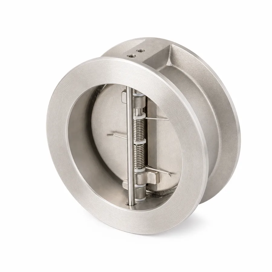
The three stainless steel wafer-type check valves in the TECTUL catalog, mounted between the two line flanges with no ends of their own: the spring-loaded single-disc wafer check (ultra-short profile), the swing-clapper wafer check (low pressure drop) and the dual-plate wafer check (two spring-loaded half-discs, the most compact and fastest closing). All three share the API 594 type A dimensional framework —the short face to face that defines the wafer/lug category against a conventional swing check valve— and none has a standalone pressure rating: it seals compressed between the line flanges, just like a butterfly valve. This sheet publishes face to face by size, the type→mounting position→cracking pressure matrix, and the physics behind why the dual-plate check displaced the swing check valve on networks with frequent pump stops.
Important: Before using these data in engineering, design or installation decisions on systems exposed to mechanical, pressure, rupture, fatigue, impact or water-hammer risk, it is essential to read the technical notice and limitation of liability at the end of this sheet.
SKU VT-cheque-wafer-disco-inoxidable (stainless wafer disc check) · family of 3 wafer-type check valve designs in stainless steel mounted between class 150 flanges
1. Technical specifications
The three designs in the TECTUL catalog
| Reference | Closing mechanism | Characteristic use |
|---|---|---|
| Stainless wafer disc check | Single disc, axially guided, pushed onto the seat by a central helical spring | Process lines where axial space between flanges is minimal; works in any orientation |
| Stainless wafer clapper check | Clapper (disc) swinging on an offset pin, with or without an auxiliary assist spring | Clean or slightly viscous fluids, where minimum head loss is prioritised over closing speed |
| Dual-plate wafer check | Two "D"-shaped half-discs hinged on a central pin, each with its own spring | Pump discharge with frequent stops: the fastest-closing design of the three |
Materials by component
| Component | Material | Designation / source of the data |
|---|---|---|
| Body | Cast stainless steel, equivalent to 316 (Cr 18–21 %, Ni 9–12 %, Mo 2–3 %) | Equivalent to ASTM A351 CF8M |
| Disc / half-discs | Cast or forged 300-series stainless steel, per figure | Exact grade: manufacturer data |
| Shaft and bushings | Hardened stainless steel or PTFE/sintered-metal wear bushing, per design | Manufacturer data |
| Closing spring | 300-series austenitic stainless steel for general service; Inconel X-750 available for high temperature (manufacturer catalog reference, not this line) | Exact grade per figure: manufacturer data |
| Seat | Integral metal-to-metal (conical seat profile) or elastomeric insert (EPDM/NBR/FKM), per figure | Manufacturer data |
Reference composition of the cast stainless steel per the ASTM A351 CF8M equivalent. The exact grade of the disc, shaft and spring per figure are manufacturer data for each reference and are confirmed on quotation or in the PDF sheet attached to the product.
Regulatory framework and supply conditions
| Valve type | Check (non-return), wafer/lug type: no ends of its own, installed compressed between two flanges |
| Body material | Cast stainless steel, ASTM A351 CF8M equivalent |
| Dimensional standard | API 594 type A (short face to face of the wafer/lug category versus type B, the long globe/API 6D body) |
| Pressure rating | That of the mating flange, class 150 ASME B16.34, with the valve correctly mounted and torqued — see section 2 |
| Ends | No flanges of its own: wafer-type body with holes or guides for through studs per ASME B16.5 class 150 |
| Catalog sizes | 2″ to 8″ depending on reference; additional sizes are confirmed on quotation |
The face-to-face dimensions published in section 2 are reference values for the API 594 type A category compiled from manufacturer tables; the certified value of each figure and size is confirmed with the PDF sheet or factory certificate.
⚠ Important: this technical data sheet is a reference guide to the product's properties; it is not a quality certificate for the product you are buying. Heats vary from one another and may differ from the values stated here, or even depart from the standards. If your application requires compliance with a standard, always check the quality certificate (mill certificate) of the lot you are buying. If in doubt, ask one of our technical advisors →
2. Face to face per API 594 type A and the pressure class of the flanged assembly
Why face to face is the first datum of a wafer check valve
API 594 —Check Valves: Flanged, Lug, Wafer and Butt-welding— defines two dimensional categories: type A, short face to face (wafer and lug, including dual-plate designs), and type B, long face to face, dimensionally equivalent to a conventional flanged gate or globe valve. The three designs in this sheet are type A: that short face to face is the reason the wafer exists —less weight, less space, less piping cost— and it is also the first datum to check before ordering, because a type A is not dimensionally interchangeable with a swing check valve or a type B of the same size.
| Size | Face to face (F2F) type A, class 150 | Source reference |
|---|---|---|
| 2″ (DN50) | 60 mm (2.36″) | Compilation of API 594 type A tables from manufacturer catalogs |
| 4″ (DN100) | 73 mm (2.87″) | Compilation of API 594 type A tables from manufacturer catalogs |
| 6″ (DN150) | 98 mm (3.86″) | Compilation of API 594 type A tables from manufacturer catalogs |
| 3″, 5″, 8″ and larger | Confirmed on quotation | Current API 594 standard; the exact value depends on the actual manufacturer of the figure |
IMPORTANT
This data sheet is a reference guide to the properties of this product type. The measurements, dimensions and physical or geometric characteristics of the product actually supplied may vary by manufacturer and lot, and may even fall outside the cited standards. If any of these figures is critical to your design or build, it is essential to verify it with one of our advisors against the physical product, so you can be fully certain of what you are buying. · Original data sheet: tectul.com/en/conduccion-de-fluidos/valvulas/ficha-tecnica-cheque-wafer-disco-inoxidable.html
The three published points (2″, 4″, 6″) are the sizes for which verifiable catalog evidence exists within the type A category. For the remaining sizes in this family's range, face to face is confirmed on quotation with the factory PDF sheet: no value is interpolated or assumed for an intermediate size.
The pressure class belongs to the flange, not to the loose valve
Like a wafer butterfly valve, none of these three designs has ends that seal on their own. The seal against the fluid is produced by the metal-to-metal fit or the elastomeric seat of the disc against the body, but the pressure the assembly withstands depends on the flanges compressing it: class 150 per ASME B16.34/B16.5, with through studs of the count and diameter of that class. Publishing "150 psi" without saying "class 150, mounted between ASME B16.5 flanges" is publishing an incomplete datum: the correct figure is that of the flange class, not a standalone rating of the check valve body.
- The pressure figure that applies to this valve is that of class 150 ASME B16.34 of the flanged assembly: 285 psig (19.6 bar) at 38 °C for carbon steel, 275 psig (19.0 bar) for CF8M stainless steel, decreasing with temperature.
- That figure only applies if the flanges are class 150, if the studs are correct for that size and if tightening was done in a cross pattern and in stages (same procedure as section 5).
- The disc's metal-to-metal or elastomeric seat additionally sets its own temperature and tightness limit that may be more restrictive than that of the flange: the lower of the two governs.
3. Type → mounting position → cracking pressure matrix
The three designs in this sheet share a short face to face, but they do not share the same opening behaviour. Mounting orientation decides how much gravity weighs against the spring, and that combination sets the cracking pressure: the minimum forward differential pressure needed to lift the disc off the seat and let flow through.
| Reference | Horizontal | Vertical, upward flow | Cracking pressure (order of magnitude) |
|---|---|---|---|
| Stainless wafer disc check | Yes — the spring closes in any orientation | Yes | ≈0.2–0.5 psi horizontal; somewhat higher vertical, where the spring must also overcome the disc's weight |
| Stainless wafer clapper check | Yes — preferred position, the clapper works with less resistance | Yes, if the design includes an auxiliary spring; without a spring, only horizontal or vertical upward flow by gravity | Very low horizontal without a spring (minimum head loss); with an auxiliary spring, same order as the disc design |
| Dual-plate wafer check | Yes | Yes | ≈0.2–0.5 psi per half-disc; closing is faster than a single disc of the same size owing to lower mass and travel per half-disc |
The cracking pressure values are order-of-magnitude catalog practice for spring-loaded disc/dual-plate check valves, not a certified figure for this line: no manufacturer surveyed in Spanish publishes cracking pressure per figure and size. The exact value per reference is confirmed on quotation with the factory PDF sheet. Vertical with downward flow is not an admissible position on any of the three designs: the disc cannot close against gravity and flow at the same time.
Why position changes cracking pressure
Horizontally, the disc's weight acts perpendicular to the closing axis and neither opposes nor assists the spring: cracking pressure is set by the spring alone. Vertically with upward flow, the disc must also overcome its own weight to lift off the seat, so effective cracking pressure rises somewhat versus horizontal —the manufacturer usually fits a slightly stiffer spring on the vertical variant, or the same spring gives a slightly higher cracking pressure—. That is why the mounting position declared on the order is not a matter of convenience: it changes the physics of how the valve opens.
Reading the arrow correctly
The arrow cast on the body marks flow direction, not mounting position. A disc or dual-plate wafer check can be mounted in any orientation as long as forward flow matches the arrow; what does demand a specific orientation is the clapper variant without an auxiliary spring, which relies on gravity to return the disc.
4. Why the dual-plate check displaced the swing check valve
The classic swing check valve —a swinging disc hung from an offset pin in a long-face-to-face flanged body— was for decades the default design on pump discharge. The dual-plate check displaced it in most of those services for three measurable reasons, not fashion:
| Weight | A type A wafer body weighs a fraction of a type B swing body of the same size: less cast material, less support structure, less handling cost on site. |
| Short face to face | Being type A, the dual-plate check frees up axial space on the line: on retrofits where the gap between flanges is already fixed by existing piping, it is often the only option that physically fits. |
| Closing speed | Each half-disc of the dual-plate check has less mass and a shorter angular travel than the single, large disc of a swing check: the spring drives it to the seat in a fraction of the time, before the flow has a chance to fully reverse. |
The physics of water hammer from slow closing
When a pump stops, the liquid column decelerates, stops and reverses toward the pump. The check valve must close before that reversal gains significant speed. A swing check closes by gravity alone: the heavy disc, with a long angular travel, takes time to fall onto the seat, and on tall columns or frequently stopping pumps that closing completes when the return flow already has speed. The abrupt stop of that moving mass is what generates the closing water-hammer overpressure (slam).
The spring of the dual-plate check —or of the single disc in this sheet— pushes the closure member toward the seat throughout the cycle, not only once gravity finally overcomes inertia: closing follows the deceleration of the flow and usually completes before the flow reverses. That is why the dual-plate check and the spring-loaded disc are recommended for pump discharge with frequent starts and stops, while the large-diameter, slow-closing swing check is now reserved for steady-flow lines without abrupt stops.
The exact magnitude of the water-hammer overpressure depends on the reverse velocity being cancelled, the pressure wave celerity in the pipe and the actual closing time of the valve: none of these is a property of the check valve itself, and this sheet does not publish an overpressure figure. The transient calculation belongs to the project engineer under the applicable code (ASME B31.1 or B31.3).
5. Mounting between flanges: studs, centering and tightening
Verification before operation
Because it has no ends of its own, mounting the flanged assembly is part of the specification of a wafer check valve, not a site detail. Three points account for nearly all field errors in this family:
- Centering. The wafer body must be coaxial with the inside diameter of the flanges: off-centre, the edge of the disc or half-discs can strike the inner face of the flange or the adjacent pipe when opening, especially on the dual-plate check, where the half-discs swing outward from the body.
- Through studs. The number and diameter of studs are set by the class 150 flange (ASME B16.5), not by the check valve body: they must be through studs, of the correct length for the valve face to face plus the two flanges, and tightened in a cross pattern and in stages (one third, two thirds, final torque, with a verifying circular pass), following ASME PCC-1 practice.
- Do not tighten onto the check valve body. The stud runs outside or through body guides, but the tightening load is carried by the flange faces, not the valve body. Uneven or excessive tightening can deform the seat —if elastomeric— or force the body into bending if the flanges were not parallel before tightening.
| Alignment | Flanges parallel and coaxial before inserting the valve; never close a misalignment by pulling on the studs. |
| Opening clearance | Verify that the disc (or half-discs) does not strike the inside diameter of the flange or adjacent pipe when fully open, particularly on large sizes or with reduced-bore flanges. |
| Flow direction | Confirm the body arrow against the actual line flow before tightening the first stud: installed backwards, the check valve stays closed against service or unprotected, depending on the design. |
| Tightening torque | Final torque per size is set by the manufacturer; confirmed on quotation. Do not use the torque of a conventional metallic joint without checking against the actual seat of the figure, whether metal-to-metal or elastomeric. |
A wafer check valve must not be used as a temporary blind flange by removing the pipe on one side: without the flange on the dismantled side, the assembly loses the compression under which its rating was tested and the valve falls outside its certified condition.
6. Frequently asked questions
How much pressure does a wafer check valve take?
The pressure the assembly withstands is that of the class of the flange compressing it, not a standalone rating of the body: class 150 ASME B16.34, 285 psig (19.6 bar) at 38 °C for carbon steel or 275 psig (19.0 bar) for CF8M stainless steel, correctly mounted and torqued between flanges. Outside the flanged assembly, the wafer check valve has no working pressure of its own.
For which sizes is the published face to face available?
This sheet publishes verified API 594 type A face to face for 2″ (60 mm), 4″ (73 mm) and 6″ (98 mm). For 3″, 5″, 8″ and larger catalog sizes, the exact value is confirmed on quotation with the factory PDF sheet.
Are the dual-plate check and the single-disc check interchangeable?
Dimensionally yes, since both are API 594 type A with equivalent face to face at the same size. Functionally they are not equal: the dual-plate check closes faster due to the lower mass and inertia of each half-disc, making it preferable on pump discharge with frequent stops; the single disc is mechanically simpler and is usually preferred where fast closing is not critical.
Can I install the wafer check valve vertically with downward flow?
No, on none of the three designs. The spring on the disc and dual-plate variants closes in any orientation as long as forward flow matches the body arrow, but none is designed to close against downward flow and gravity simultaneously; the clapper variant without an auxiliary spring also relies on gravity for the return, so it requires horizontal or vertical upward flow.
What tightening torque do the studs of a wafer check valve carry?
Whatever the manufacturer sets for the size and seat type (metal-to-metal or elastomeric), applied in a cross pattern and in stages following ASME PCC-1. The exact value is confirmed on quotation; do not assume the torque of a conventional metallic joint without checking against the actual seat of the figure.
7. Application notes
Feasibility
The three stainless wafer designs cover clean process lines, treated water and pump discharge with frequent stops, mounted between class 150 (ASME B16.34) flanges within the catalog's 2″–8″ range. The dual-plate check is the natural reference where slow-closing water hammer is a concern; the clapper without a spring, where minimum head loss outweighs closing speed. Out of scope: large-diameter service (above 8″), for which the type B flanged check or the ductile iron swing check applies, each with its own data sheet; and any application where the manufacturer does not confirm the exact face to face or cracking pressure of the requested figure.
Installation
Check the flow-direction arrow against the actual flow before tightening the first stud. Centre the wafer body relative to the flange inside diameter and check the opening clearance of the disc or half-discs against the adjacent pipe. Tighten the through studs in a cross pattern and in stages per ASME PCC-1, at the torque the manufacturer states for the size and seat type; do not close misalignments by pulling on the studs. Leave a straight run upstream free of elbows and immediate reducers so the disc does not chatter. Do not use the valve as a temporary blind flange.
Design
Specify the wafer check valve together with its flanged assembly: flange class, studs and tightening torque are part of the specification. Choose the mechanism by the pump's operating profile: dual-plate or spring-loaded disc where stops are frequent and water hammer is a risk; clapper where minimum head loss in steady flow is the priority. Face to face and cracking pressure for sizes not published in section 2 are confirmed on quotation before fixing the piping layout, because type A is not dimensionally interchangeable with a type B or a swing check valve of the same size.
8. Technical notice and limitation of liability
The dimensional framework of this sheet combines API 594 (type A category, short wafer/lug face to face) and ASME B16.34/B16.5 (pressure class and mating flange) with manufacturer catalog evidence compiled for the 2″, 4″ and 6″ sizes. For 3″, 5″, 8″ and larger sizes, the exact face to face and cracking pressure are not published by the manufacturer and are confirmed on quotation with the factory certificate or PDF sheet: the value of an unlisted size must not be assumed from the published ones.
The cracking pressure values in section 3 are order-of-magnitude catalog practice for spring-loaded disc and dual-plate check valves, not a certified figure for this line. Section 4 on water hammer is qualitative: it gives no overpressure figures because the transient depends on the line, the pumping set and the actual closing time, not on the valve.
These values must not be used as the sole criterion in critical or safety applications, or wherever valve failure may compromise people, property or the environment: in such cases the design belongs to the project's responsible engineer under the applicable code. Before deciding with these data, consult our technical team.
Sources
- API 594 — Check Valves: Flanged, Lug, Wafer and Butt-welding: categorías dimensionales tipo A (cara a cara corta) y tipo B (cara a cara larga)
- ASME B16.34 — Valves — Flanged, Threaded and Welding End: clase 150, ratings presión-temperatura para acero al carbono y acero inoxidable CF8M
- ASME B16.5 — Pipe Flanges and Flanged Fittings: bridas de acoplamiento clase 150, círculo de pernos y número de espárragos
- ASME PCC-1 — Guidelines for Pressure Boundary Bolted Flange Joint Assembly: secuencia cruzada y apriete por etapas
- ASTM A351/A351M — Standard Specification for Castings, Austenitic, for Pressure-Containing Parts: composición de referencia del acero inoxidable fundido CF8M
- Compilación de tablas de cara a cara API 594 tipo A de catálogos de fabricantes de válvulas de retención wafer/dúo disco (wermac.org y catálogos técnicos equivalentes) — evidencia de catálogo, no norma primaria
- Crane Co. — Flow of Fluids Through Valves, Fittings and Pipe (Technical Paper No. 410): principio de dimensionamiento de válvulas de retención por velocidad mínima de apertura plena
- ASME B31.1 / ASME B31.3 — códigos de tubería de potencia y de proceso: marco al que corresponde el análisis del transitorio hidráulico citado en la sección 4
- Curaduría interna TECTUL (data/etapas/etapa-1-conduccion-de-fluidos/curaduria.json) — referencias y diámetros por producto, agosto 2026
This data sheet is the property of TECTUL, part of the Industrias IMR group. Reproduction without attribution is prohibited. Original document and updates: tectul.com/en/conduccion-de-fluidos/valvulas/ficha-tecnica-cheque-wafer-disco-inoxidable.html.