 TECTULby IMR
Bronze angle valve for fire hose cabinets — 300 PSI, UL Listed and FM Approved
TECTUL · Dispatch across Colombia · Exports to Central & South America
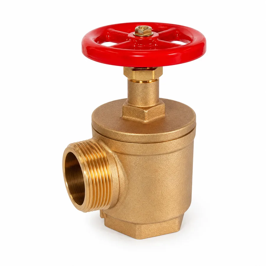
Bronze angle valve for hose connection in a fire cabinet, with a 90° cast angle body and globe mechanism (axial disc on a seat in the flow path). The manufacturer declares it UL Listed and FM Approved with a 300 PSI rating, a value that in the MSS SP-80 dual class system corresponds to the WOG of Class 150, whose saturated steam pair is 150 psig at ≈186 °C. It is offered in 1-1/2″ and 2-1/2″ (DN 40 and DN 65), with three variants in the catalog. It is the only reference in the catalog's threaded bronze family with a declared third-party certification, and that certification — not the material — is what qualifies it for a fire protection system.
Important: Before using these data in engineering, design or installation decisions on systems exposed to mechanical, pressure, rupture, fatigue, impact or water-hammer risk, it is essential to read the technical notice and limitation of liability at the end of this sheet.
SKU VT-59177 (bronze angle valve) · 1 UL Listed and FM Approved reference, 300 PSI, in 1-1/2″ and 2-1/2″ with 3 catalog variants
1. Technical specifications
Materials by component
| Component | Material | Designation / standard |
|---|---|---|
| 90° angle body and bonnet | Cast bronze, 85-5-5-5 alloy (84–86 % Cu, 4–6 % Sn, 4–6 % Pb, 4–6 % Zn) | ASTM B62, alloy C83600 |
| Closure member (disc) | Disc seating axially on the seat, globe-type mechanism, guided by the stem | ASTM B62 C83600 |
| Seat | Integral to the body, metal-to-metal closure, or with a soft insert depending on the figure | Machined on the body |
| Stem / screw | Bronze; high-strength brass on some figures | Copper alloy, manufacturer grade |
| Gland | Brass | ASTM B16, alloy C36000 |
| Stem packing | PTFE, asbestos-free | PTFE packing |
| Handwheel | Ductile iron with galvanized steel nut, or cabinet-type handwheel depending on the figure | ASTM A536 |
| Inlet | Female tapered NPT thread | ASME B1.20.1 |
| Hose outlet | Fire hose thread per the standard adopted by the system; confirmed on quotation | Project hose thread standard |
C83600 composition per ASTM B62. The exact hose outlet thread standard, the seat type and the presence of a protective cap or plug are manufacturer data per figure and must match the rest of the cabinet equipment and the building's fire hose thread standard: confirmed on quotation.
Standards and service framework
| Declared third-party certification | UL Listed (Underwriters Laboratories) and FM Approved (FM Approvals) — see section 3 |
| Rating published by the manufacturer | 300 PSI (20.7 bar), cold non-shock pressure |
| Equivalence in the dual system | MSS SP-80 Class 150: 300 psi WOG cold / 150 psig SWP with saturated steam at ≈186 °C (see section 2) |
| Family design standard | MSS SP-80 — Bronze Gate, Globe, Angle and Check Valves |
| Geometry | Cast 90° angle body with globe mechanism: direction change and closure member in a single part (see section 4) |
| Application | Hose connection in a fire cabinet; water take-off from a standpipe or protection main |
| Installation code | That of the building's fire protection system: NFPA and the applicable local regulation. This sheet does not replace that code |
Angle valve reference in the TECTUL catalog
| Reference | Sizes | Catalog variants | Rating and certification |
|---|---|---|---|
| Bronze angle valve (SKU VT-59177) | 1-1/2″ (DN 40) and 2-1/2″ (DN 65) | 3 (2-1/2″ appears in two presentations) | 300 PSI · UL Listed · FM Approved |
IMPORTANT
This data sheet is a reference guide to the properties of this product type. The measurements, dimensions and physical or geometric characteristics of the product actually supplied may vary by manufacturer and lot, and may even fall outside the cited standards. If any of these figures is critical to your design or build, it is essential to verify it with one of our advisors against the physical product, so you can be fully certain of what you are buying. · Original data sheet: tectul.com/en/conduccion-de-fluidos/valvulas/ficha-tecnica-valvula-angular-bronce.html
The two 2-1/2″ presentations in the catalog differ in finish or outlet thread details that must be verified against the cabinet equipment: the correct presentation is confirmed on quotation. Face-to-face dimensions and weight by size are not standardized by MSS SP-80 for threaded bronze valves and are manufacturer data.
⚠ Important: this technical data sheet is a reference guide to the product's properties; it is not a quality certificate for the product you are buying. Heats vary from one another and may differ from the values stated here, or even depart from the standards. If your application requires compliance with a standard, always check the quality certificate (mill certificate) of the lot you are buying. If in doubt, ask one of our technical advisors →
2. How to read the "300 PSI" on this valve
The manufacturer publishes 300 PSI for this reference. Within the MSS SP-80 framework, which rates bronze gate, globe, angle and check valves with dual classes, that figure is a WOG — cold, non-shock pressure — and corresponds to Class 150.
| MSS SP-80 class | SWP — saturated steam | Saturation temperature at that SWP¹ | WOG — cold, ≤38 °C |
|---|---|---|---|
| 125 | 125 psig (8.6 bar) | ≈178 °C (353 °F) | 200 psi (13.8 bar) |
| 150 ← this valve | 150 psig (10.3 bar) | ≈186 °C (366 °F) | 300 psi (20.7 bar) |
| 200 | 200 psig (13.8 bar) | ≈198 °C (388 °F) | 400 psi (27.6 bar) |
| 300 | 300 psig (20.7 bar) | ≈216 °C (421 °F) | 600 psi (41.4 bar) |
IMPORTANT
This data sheet is a reference guide to the properties of this product type. The measurements, dimensions and physical or geometric characteristics of the product actually supplied may vary by manufacturer and lot, and may even fall outside the cited standards. If any of these figures is critical to your design or build, it is essential to verify it with one of our advisors against the physical product, so you can be fully certain of what you are buying. · Original data sheet: tectul.com/en/conduccion-de-fluidos/valvulas/ficha-tecnica-valvula-angular-bronce.html
¹ Saturation temperature of steam at the stated SWP: it is a thermodynamic property of water, not of the valve. It is the same reference value ASME B16.3-2021 (Table 3-1, note 1) uses for the 186 °C limit of class 150 threaded fittings. Mind the numerical coincidence: 300 PSI (WOG) is Class 150, whereas Class 300 is a different thing — it allows 300 psig of steam and 600 psi WOG cold. The same number means different things depending on the column.
What it means in the real service of a fire cabinet
| Condition | Applicable limit | Value | Comment |
|---|---|---|---|
| Fire main water, ambient temperature | WOG | 300 psi · 20.7 bar | This is the valve's normal service condition: cold water, static most of the time |
| System hydrostatic test pressure | As set by the building's installation code | Checked against the valve's 300 psi | Acceptance tests of a fire protection system are run above working pressure: the margin against 300 psi must be verified |
| Water hammer when closing the hose | Neither: it is a design load case | Calculated separately | The WOG is explicitly "non-shock"; abrupt closure of a hose valve at high flow generates significant transients |
| Saturated steam | Class 150 SWP | 150 psig at ≈186 °C | Irrelevant for fire service; included so the label is read correctly |
IMPORTANT
This data sheet is a reference guide to the properties of this product type. The measurements, dimensions and physical or geometric characteristics of the product actually supplied may vary by manufacturer and lot, and may even fall outside the cited standards. If any of these figures is critical to your design or build, it is essential to verify it with one of our advisors against the physical product, so you can be fully certain of what you are buying. · Original data sheet: tectul.com/en/conduccion-de-fluidos/valvulas/ficha-tecnica-valvula-angular-bronce.html
- Starting data: cabinet at the lowest level of a standpipe serving 12 floors, with the fire pump downstream of the tank.
- Static pressure from the column: a 40 m water column equals
p = ρ·g·h = 1000 × 9.81 × 40 = 3.92 × 10⁵ Pa = 3.92 bar ≈ 57 psi. On its own it does not compromise the valve. - Pump discharge pressure: if the pump delivers 150 psi at its discharge, the ground floor cabinet sees ≈150 + 57 = 207 psi in the worst static case. Still below the 300 psi WOG.
- Hydrostatic acceptance test: run above working pressure per the applicable code. This is where the margin narrows and where the code-required value must be confirmed before accepting the valve.
- Transient: abrupt closure of a 2-1/2″ hose at high flow produces a peak added to the static pressure. It is not covered by the WOG and must be evaluated by the system designer.
- Conclusion: the 300 psi comfortably covers the typical static service of a cabinet, but the formal verification is made by the fire protection engineer against the test pressure and the transients of the actual system, not by this sheet.
3. UL Listed and FM Approved: what they certify and why they are a code requirement
On an ordinary industrial valve, third-party certification is optional. On a fire protection component it is not: fire protection installation codes require equipment to be listed or approved for the service in which it is used. A cabinet angle valve without that condition is not simply "a cheaper option": it is equipment the authority having jurisdiction may reject at system acceptance.
What each one is
| UL Listed | FM Approved | |
|---|---|---|
| Who issues it | Underwriters Laboratories, a safety testing and certification laboratory | FM Approvals, the certification arm of the industrial insurer FM |
| What it means | That samples of the product were tested against an applicable product standard — for fire protection hose valves, the corresponding UL standard for this type of device — and that the product appears in UL's directory of listed products | That the product passed the performance tests of the FM Approval Standard applicable to its category and appears in the FM approval guide |
| What is tested, in essence | Pressure resistance, tightness, cycling durability, material resistance and performance under the device's intended service conditions | Equivalent performance from the insurer's standpoint: reliability of the component in the fire scenario and over time |
| What it guarantees beyond the initial test | Factory follow-up. It is not a one-off test: it involves periodic audits of the plant to verify that production remains the same as what was tested | The same: approval is maintained through continuous surveillance of the manufacturer and its production |
| How it is verified | Marking on the product and a search in the certifier's directory — certification belongs to the specific model and manufacturer, not to the product category | Marking on the product and a search in the FM Approvals guide, likewise by model and manufacturer |
Why this is not commercial ornamentation
- It is a code requirement, not a supplier requirement. Fire protection regulation — the NFPA standards applicable to the building's system and the local regulation adopting them — requires listed or approved components. Without them, the installation may not be accepted.
- It certifies performance in a scenario almost never tested on site. A cabinet valve stays closed for years and must open and seal reliably on the day of the fire. That behaviour cannot be verified at material receipt: third-party certification is the only practical evidence.
- It implies continuous factory surveillance. That is the difference between "one batch passed a test" and "production is under permanent audit".
- It has insurance consequences. FM Approval comes precisely from the insurance world: in industrial policies, the use of approved components can be a condition of the risk.
- It is model-specific. A manufacturer having listed products does not make its whole line listed. Verification is done by model and size, against the product marking and the certifier's directory.
Scope of this sheet. The UL Listed and FM Approved condition with a 300 PSI rating is data published by the manufacturer on this product page. TECTUL supplies the component; the design, calculations, size selection, test pressure verification and system acceptance belong to the project's fire protection engineer, under the applicable NFPA standard and the building's local regulation. This sheet does not replace that code or that design. Current certificates for the specific model and size are requested on quotation.
4. The angle body: elbow and valve in a single part
An angle valve is, mechanically, a globe valve whose body takes the fluid in at one end and out at 90°. The mechanism is the same — an axial disc seating on a seat located in the flow path — but instead of rising and descending again inside the chamber, the fluid enters, turns once and leaves. That geometric difference has three practical consequences.
1. It saves a fitting and a threaded joint
In a fire cabinet the water arrives through a vertical standpipe and must leave horizontally towards the hose. Without an angle valve, two parts would be needed: a 90° elbow plus a valve. With the angle valve, the direction change and the closure member live in a single casting. That means: one threaded joint fewer — that is, one fewer potential leak point in a system that stays pressurized for years — less space inside the cabinet, less cantilevered weight on the piping, and one fewer assembly to make and check on site.
2. It loses considerably less pressure than elbow + globe
Using the resistance coefficient model of Crane TP-410, fully open parts are represented as follows:
| Component | Resistance coefficient K | Comment |
|---|---|---|
| Angle valve, fully open | K = 55·fT | A single direction change and a single restriction |
| Globe valve, fully open | K = 340·fT | The fluid rises, crosses the seat and descends again: two internal 90° turns |
| Standard 90° elbow | K = 30·fT | The fitting the angle valve makes unnecessary |
| Gate valve, fully open | K = 8·fT | Comparison reference: practically full bore |
- Option A (angle valve):
K = 55·fT. - Option B (90° elbow + globe valve):
K = 30·fT + 340·fT = 370·fT. - Ratio:
370 / 55 = 6.7→ the elbow-plus-globe solution opposes 6.7 times more resistance than the angle valve. - In figures: 2-1/2″ (DN 65) line with water at 3.0 m/s. Velocity head
v²/2g = 3.0² / (2 × 9.81) = 0.459 m; fully turbulent friction factorfT ≈ 0.018for 2-1/2″ commercial steel.
Angle valve:K = 55 × 0.018 = 0.99→h = 0.99 × 0.459 = 0.45 m.
Elbow + globe:K = 370 × 0.018 = 6.66→h = 6.66 × 0.459 = 3.06 m. - Reading: roughly 2.6 m of water column less at the hose take-off, which translates directly into pressure available at the nozzle. In a system where residual pressure at the most unfavourable point is the design criterion, that difference matters.
The coefficients K = 55·fT (open angle valve), K = 340·fT (open globe valve), K = 30·fT (standard 90° elbow) and K = 8·fT (open gate valve) are reference values from the Crane Technical Paper No. 410 method for fully open parts; the actual value of each figure depends on the manufacturer's internal design. If residual pressure at the most unfavourable point is critical, it must be verified against the Cv or K published by the manufacturer of the specific model and against the system's hydraulic calculation.
3. The hose connection and cabinet mounting
- Thread compatibility. The outlet carries a fire hose thread per the standard adopted by the building's system, which must match that of the cabinet's hoses, nozzles and adapters and that of the city fire department. This is the point that causes most trouble on site: a correct valve with the wrong thread is useless. Confirmed on quotation.
- Orientation. The inlet threads onto the standpipe and the outlet faces the front of the cabinet, with clear space to couple the hose and turn the handwheel without obstruction from the door or the hose rack support.
- Inlet thread. NPT seals by tapered metal-to-metal interference (ASME B1.20.1); PTFE tape or paste fills the helices and lubricates the make-up. Apply it on the male thread, never on the female, and without intruding into the bore. Tighten with a wrench on the body, never by the handwheel.
- Outlet protection. Keep the protective cap or plug on the outlet while the cabinet is not in use: it prevents dirt ingress and protects the hose thread from impact.
- Operation and maintenance. Open slowly: abrupt opening or closing of a hose at high flow generates pressure transients. Inspection, testing and maintenance routines for the cabinet are set by the system programme under the applicable NFPA standard, not by this sheet. A drip at the stem is corrected by gradually tightening the gland.
5. Frequently asked questions
What does it mean for a valve to be "UL Listed and FM Approved"?
That samples of that specific model were tested by an independent body — Underwriters Laboratories for the UL Listing, FM Approvals for the FM Approval — against the product standard applicable to its category, that the product appears in the body's directory, and that the factory is subject to periodic audits verifying that production remains as tested. It is not a one-off test or a commercial badge: it is certification with factory follow-up, and it is specific to the model and manufacturer, not to the whole line.
Can I install a non-certified angle valve in a fire cabinet?
Fire protection codes require listed or approved components for the service, and the authority having jurisdiction may reject the installation if they are not. The decision is not made by the supplier or by this sheet: it is set by the NFPA standard applicable to the building's system and by local regulation, and verified by the project's fire protection engineer.
What does the "300 PSI" on this valve mean?
It is a WOG: maximum cold, non-shock pressure (up to 38 °C). In the MSS SP-80 dual class system it corresponds to Class 150, whose saturated steam pair is 150 psig at ≈186 °C. Mind the numerical coincidence: 300 PSI (WOG) is Class 150; Class 300 is a different thing and allows 600 psi WOG. The "non-shock" matters: water hammer from abruptly closing a hose is not covered by that figure.
Why an angle valve instead of an elbow with a globe valve?
For three reasons. It saves a threaded joint — one fewer leak point in a system pressurized for years — and space inside the cabinet. It loses far less pressure: using the Crane TP-410 method, the open angle valve is K = 55·fT against 370·fT for the elbow-plus-globe assembly, roughly 6.7 times less resistance, which on a 2-1/2″ outlet with water at 3 m/s equals about 2.6 m of extra water column available at the nozzle. And it is the component that the UL/FM certification covers as an assembly.
Does the outlet thread fit any hose?
No. The fire hose thread must match the standard adopted by the building's system and that of the cabinet's hoses, nozzles and adapters and of the city fire department. It is the most frequent site error with these valves. The thread standard of the reference is confirmed on quotation.
Which sizes are available and what is each one used for?
The catalog offers 1-1/2″ (DN 40) and 2-1/2″ (DN 65), with three variants — 2-1/2″ appears in two presentations differing in details to be verified against the cabinet equipment. Size selection per take-off point is not a commercial preference: it is set by the system's hydraulic calculation and the applicable NFPA standard, under the project engineer's responsibility.
6. Application notes
Feasibility
This bronze angle valve is intended for hose connection in fire cabinets, with 300 PSI WOG (Class 150 of the MSS SP-80 dual system) and a declared UL Listed and FM Approved condition. Its viability on a project is not determined by the rating alone: it is determined by the NFPA standard applicable to the building's system and by local regulation, which require listed or approved components and set the size and required residual pressure at each take-off point. For industrial throttling services outside fire protection, the catalog offers bronze and CF8M globe valves with their own data sheets. For pressures above 300 psi WOG or sizes other than 1-1/2″ and 2-1/2″, a different line applies.
Installation
Verify first of all that the hose outlet thread matches the building system's standard and the cabinet's hoses, nozzles and adapters: it is the most frequent site error with these valves. The inlet threads onto the standpipe with NPT (ASME B1.20.1), which seals by tapered metal-to-metal interference; apply PTFE tape or paste on the male thread, never on the female, without intruding into the bore, and tighten with a wrench on the body, never by the handwheel. Orient the outlet towards the front of the cabinet with clear space to couple the hose and turn the handwheel without obstruction from the door or the hose rack. Keep the protective cap or plug on the outlet while the cabinet is not in use. The mounting arrangement, the inspection, testing and maintenance programme and system acceptance are set by the applicable NFPA standard and the building's local regulation.
Design
The design of the fire protection system — hydraulic calculation, size selection per take-off point, required residual nozzle pressure, acceptance test pressure and verification of the listing or approval condition of each component — belongs to the project's fire protection engineer, under the applicable NFPA standard and the building's local regulation. This sheet provides component data and does not replace that design or that code. The 300 PSI rating is a cold, non-shock pressure: transients from abrupt hose closure and from fire pump start and stop must be evaluated separately. The UL/FM certification is specific to the model and size; it must be verified against the product marking and the certifier's directory, and current certificates are requested on quotation.
7. Technical notice and limitation of liability
The UL Listed and FM Approved condition and the 300 PSI rating are data published by the manufacturer on this product page. Certification is specific to the particular model and size: it must be verified against the product marking and the certifying body's directory, and current certificates are requested on quotation. Sizes and variants come from the data TECTUL publishes (August 2026).
The 300 PSI rating is a WOG: cold pressure (≤38 °C) and non-shock. Water hammer from abrupt hose closure, transients from fire pump start and stop and the hydrostatic acceptance test pressure are not covered by that figure and are calculated separately. The resistance coefficients quoted (K = 55·fT angle, 340·fT globe, 30·fT elbow, 8·fT gate) are reference values from the Crane TP-410 method for fully open parts.
This is a component of a fire protection system, where failure compromises lives and property. The data in this sheet must not be used as the sole criterion and do not replace the code: the design, size selection, hydraulic calculation, test pressure, verification of each component's certification and system acceptance belong to the project's fire protection engineer under the applicable NFPA standard and the building's local regulation. Before deciding with these data, consult our technical team and the system designer.
Sources
- Ficha de producto TECTUL (tectul.com): Válvula Angular Bronce (SKU VT-59177) — fuente primaria de la condición Listada UL y Aprobada FM, del rating de 300 PSI, de los diámetros y variantes publicados
- MSS SP-80 — Bronze Gate, Globe, Angle and Check Valves (sistema de clases duales SWP/WOG 125/150/200/300; la norma cubre explícitamente las válvulas angulares de bronce. Alcance confirmado vía GlobalSpec y catálogo técnico WALWORTH Industrial Bronze Valves 2017)
- ASTM B62 — Standard Specification for Composition Bronze or Ounce Metal Castings, aleación C83600 (84–86 % Cu, 4–6 % Sn, 4–6 % Pb, 4–6 % Zn) — cuerpo, bonete y disco
- ASTM B16/B16M — Standard Specification for Free-Cutting Brass Rod, Bar and Shapes, aleación C36000 — prensaestopas
- ASME B1.20.1 — Pipe Threads, General Purpose, Inch (rosca NPT cónica de la entrada)
- ASME B16.3-2021, Tabla 3-1, nota (1) — referencia de la temperatura de vapor saturado a 150 psig (186 °C), el par SWP de la Clase 150 a la que corresponde el 300 PSI WOG de esta válvula
- Tablas de vapor saturado (propiedad termodinámica agua/vapor, fuente tipo NIST/ASME Steam Tables) — temperaturas de saturación a 125/150/200/300 psig
- Crane Co., Technical Paper No. 410 — Flow of Fluids Through Valves, Fittings and Pipe: coeficientes de resistencia de piezas totalmente abiertas (angular K = 55·fT, globo K = 340·fT, codo estándar de 90° K = 30·fT, compuerta K = 8·fT) y factores de fricción fT en régimen totalmente turbulento por diámetro
- Underwriters Laboratories — programa de Listing: ensayo de muestras contra la norma de producto aplicable, inclusión en el directorio de productos listados y seguimiento periódico de fábrica
- FM Approvals — programa de Approval: ensayo contra el Approval Standard aplicable a la categoría, inclusión en la guía de productos aprobados y vigilancia continua del fabricante
- Estándares NFPA de protección contra incendio aplicables al sistema del edificio y reglamentación local que los adopta — marco que exige componentes listados o aprobados y fija diámetros, presiones residuales y pruebas de aceptación (referencia normativa; el diseño corresponde al ingeniero del proyecto)
- Curaduría interna TECTUL (data/etapas/etapa-1-conduccion-de-fluidos/curaduria.json) — diámetros y variantes por referencia, agosto 2026
This data sheet is the property of TECTUL, part of the Industrias IMR group. Reproduction without attribution is prohibited. Original document and updates: tectul.com/en/conduccion-de-fluidos/valvulas/ficha-tecnica-valvula-angular-bronce.html.