 TECTULby IMR
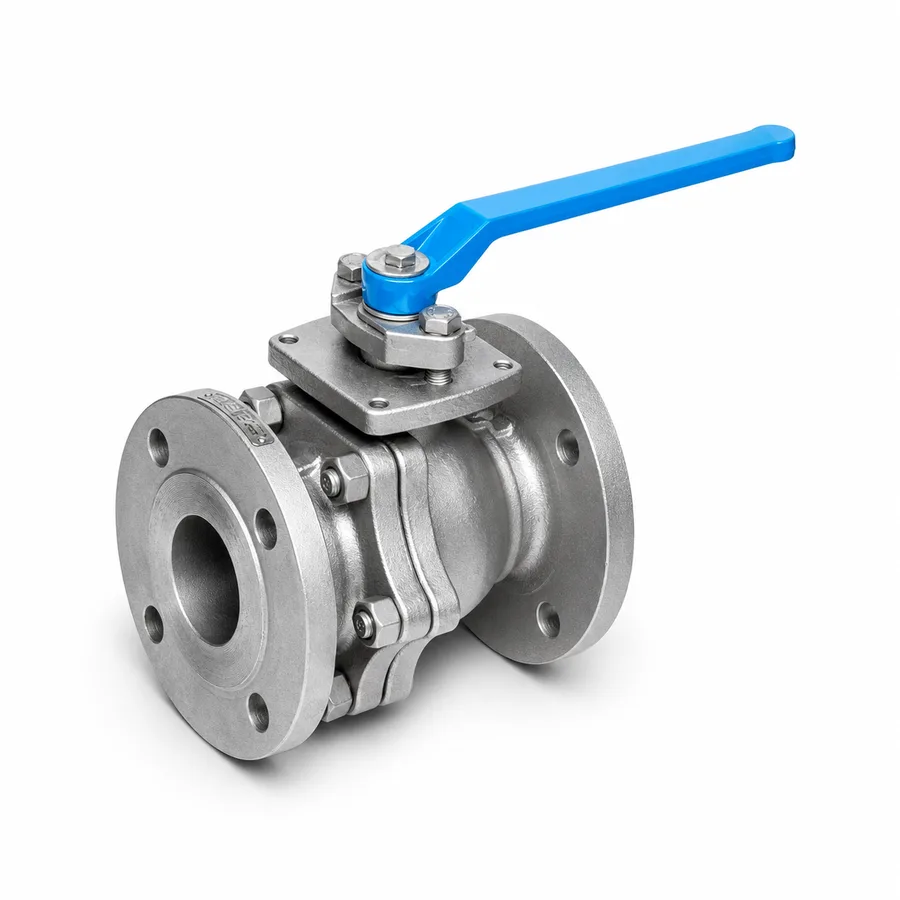
Class 150 flanged ball valve in cast stainless steel ASTM A351 CF8M — full port, API 608 design
TECTUL · Dispatch across Colombia · Exports to Central & South America
Class 150 flanged ball valve in cast stainless steel ASTM A351 CF8M, floating full-port ball, ends per ASME B16.5 raised face and face to face per ASME B16.10, designed and built to API 608 and factory-tested per API 598. The point this sheet corrects against commercial intuition: stainless does not deliver more pressure than carbon steel at the same temperature — in ASME B16.34 material group 2.2, class 150 in CF8M takes 275 psig at 38 °C, slightly below the 285 psig of carbon WCB, and both curves converge above 260 °C. The real reason to choose CF8M is twofold: corrosion resistance and a higher service temperature ceiling — up to 450 °C, versus carbon steel's practical 427 °C limit due to graphitization risk.
Important: Before using these data in engineering, design or installation decisions on systems exposed to mechanical, pressure, rupture, fatigue, impact or water-hammer risk, it is essential to read the technical notice and limitation of liability at the end of this sheet.
SKU VT-valvula-bola-inoxidable-bridada · class 150 flanged ball valve in cast stainless steel ASTM A351 CF8M
1. Technical specifications
Materials by component
| Component | Material | Designation |
|---|---|---|
| Body and cap | Cast stainless steel, grade CF8M — cast equivalent of AISI 316: Cr 18–21 %, Ni 9–12 %, Mo 2–3 %, C ≤0.08 % | ASTM A351/A351M |
| Ball | Cast CF8M or wrought 300-series stainless steel, per figure | Exact grade: manufacturer data |
| Stem | 300-series stainless steel, anti-static and blow-out proof | ASTM A276/A182 grade F316, typical |
| Seat | PTFE or fiberglass-reinforced PTFE (RPTFE) | Usual service thermal limit ≈180 °C |
| Stem packing | PTFE or graphite, asbestos-free | Asbestos-free |
| Flange studs and nuts | Stainless steel or alloy steel per project specification | ASTM A193 grade B8/B8M typical in stainless |
| Ends | Flanged, raised face | ASME B16.5 class 150 |
CF8M composition and its equivalence with 316 per ASTM A351. The exact grade of the ball, stem and studs per figure is manufacturer data and is confirmed on quotation or in the PDF sheet attached to the product.
Regulatory framework and supply conditions
| Valve type | Floating full-port ball, quarter turn, two- or three-piece flanged per figure |
| Design and construction | API 608 — Metal Ball Valves: Flanged, Threaded, and Welding Ends |
| Pressure-temperature rating | ASME B16.34, class 150, material group 2.2 (CF8M) |
| Ends | Flanged raised face, ASME B16.5 class 150 |
| Face to face (F2F) | ASME B16.10, short pattern for flanged ball valve |
| Factory testing | API 598 — shell and seat (section 2) |
| Catalog sizes | 1/2″ to 12″ (DN 15 to DN 300) |
| Port | Full (bore equal to pipe nominal diameter), floating ball design |
Flange and face-to-face dimensions by size
| Size | Face to face (F2F, short pattern) | Bolt circle Ø | Number of studs | Stud Ø |
|---|---|---|---|---|
| 1/2″ (DN 15) | 108 mm (4.25″) | 60.5 mm (2.38″) | 4 | 1/2″ |
| 3/4″ (DN 20) | 117 mm (4.61″) | 69.9 mm (2.75″) | 4 | 1/2″ |
| 1″ (DN 25) | 127 mm (5.00″) | 79.2 mm (3.12″) | 4 | 1/2″ |
| 1-1/4″ (DN 32) | 140 mm (5.51″) | 88.9 mm (3.50″) | 4 | 1/2″ |
| 1-1/2″ (DN 40) | 165 mm (6.50″) | 98.6 mm (3.88″) | 4 | 1/2″ |
| 2″ (DN 50) | 178 mm (7.00″) | 120.7 mm (4.75″) | 4 | 5/8″ |
| 2-1/2″ (DN 65) | 190 mm (7.48″) | 139.7 mm (5.50″) | 4 | 5/8″ |
| 3″ (DN 80) | 203 mm (7.99″) | 152.4 mm (6.00″) | 4 | 5/8″ |
| 4″ (DN 100) | 229 mm (9.02″) | 190.5 mm (7.50″) | 8 | 5/8″ |
| 6″ (DN 150) | 267 mm (10.51″) | 241.3 mm (9.50″) | 8 | 3/4″ |
| 8″ (DN 200) | 292 mm (11.50″) | 298.5 mm (11.75″) | 8 | 3/4″ |
| 10″ (DN 250) | 330 mm (12.99″) | 362.0 mm (14.25″) | 12 | 7/8″ |
| 12″ (DN 300) | 356 mm (14.02″) | 431.8 mm (17.00″) | 12 | 7/8″ |
IMPORTANT
This data sheet is a reference guide to the properties of this product type. The measurements, dimensions and physical or geometric characteristics of the product actually supplied may vary by manufacturer and lot, and may even fall outside the cited standards. If any of these figures is critical to your design or build, it is essential to verify it with one of our advisors against the physical product, so you can be fully certain of what you are buying. · Original data sheet: tectul.com/en/conduccion-de-fluidos/valvulas/ficha-tecnica-valvula-bola-inoxidable-bridada.html
Same dimensional pattern as this family's carbon steel line (ASME B16.5/B16.10 class 150): the flange and face to face do not change with the body material. The flow coefficient (Cv) is not published by the manufacturer for this line and is confirmed on quotation.
⚠ Important: this technical data sheet is a reference guide to the product's properties; it is not a quality certificate for the product you are buying. Heats vary from one another and may differ from the values stated here, or even depart from the standards. If your application requires compliance with a standard, always check the quality certificate (mill certificate) of the lot you are buying. If in doubt, ask one of our technical advisors →
2. Group 2.2 rating: why stainless does not give more pressure at the same temperature
Commercial intuition assumes that moving to stainless "upgrades" a valve's performance across the board, including pressure. In ASME B16.34 class 150, that is not accurate: material group 2.2 (CF8M) has a slightly lower rating than group 1.1 (WCB) at the same temperature, until both curves converge at high temperature.
| Temperature | Group 1.1 — WCB (carbon steel) | Group 2.2 — CF8M (stainless steel) |
|---|---|---|
| −29 °C to 38 °C (−20 °F to 100 °F) | 285 psig (19.6 bar) | 275 psig (19.0 bar) |
| 93 °C (200 °F) | 260 psig (17.9 bar) | 235 psig (16.2 bar) |
| 149 °C (300 °F) | 230 psig (15.9 bar) | 215 psig (14.8 bar) |
| 204 °C (400 °F) | 200 psig (13.8 bar) | 195 psig (13.4 bar) |
| 260 °C (500 °F) | 170 psig (11.7 bar) | 170 psig (11.7 bar) |
| 316 °C (600 °F) | 140 psig (9.7 bar) | 140 psig (9.7 bar) |
IMPORTANT
This data sheet is a reference guide to the properties of this product type. The measurements, dimensions and physical or geometric characteristics of the product actually supplied may vary by manufacturer and lot, and may even fall outside the cited standards. If any of these figures is critical to your design or build, it is essential to verify it with one of our advisors against the physical product, so you can be fully certain of what you are buying. · Original data sheet: tectul.com/en/conduccion-de-fluidos/valvulas/ficha-tecnica-valvula-bola-inoxidable-bridada.html
Pressure-temperature table per ASME B16.34, material groups 1.1 (WCB) and 2.2 (CF8M), class 150. Between 38 °C and 204 °C carbon steel delivers more psig than stainless; from 260 °C on, both curves are equal within the table's resolution. At no point in this range does stainless exceed carbon steel in pressure.
The real differentiator: the temperature ceiling, not the psig figure
The reason to prefer CF8M is not a higher pressure figure at moderate temperature, but two different factors:
- Corrosion resistance (developed in the selection criteria of this series' sibling sheets): the molybdenum in CF8M resists chlorides, chemicals and aggressive environments where carbon steel would pit or rust, regardless of pressure.
- Higher service temperature ceiling: carbon steel WCB has a practical service limit of 427 °C (800 °F), above which the manufacturer does not recommend prolonged use due to graphitization risk (transformation of the steel's carbides, which embrittles the material over time at that temperature). The stainless CF8M line, by contrast, retains a valid rating in ASME B16.34 up to 450 °C (842 °F), without that metallurgical restriction. In other words: above 427 °C carbon steel falls outside recommended service even if the table still assigned it a residual pressure, while stainless still has a valid table point 23 °C higher.
- If the service is water, air or non-corrosive oils below 400 °C and budget governs: carbon steel (FT-TC-VAL-BOLAB-CARBON-001) delivers equal or higher pressure at the same temperature and costs less.
- If the fluid or environment attacks carbon steel (chlorides, chemicals, coastal environments): CF8M, regardless of temperature.
- If the service requires temperature above 427 °C: CF8M, because carbon steel is no longer a recommended option at that point, even if the required pressure is low.
- Above 180 °C, in either material, the real limit reverts to the PTFE seat, not the body: sustained high-temperature service requires a different seat, confirmed on quotation.
CF8M is not exactly wrought 316: it is its cast equivalent, with the same nominal chemical composition but obtained by casting rather than forging, which introduces metallurgical grain and admissible porosity differences versus the wrought material used in stems and studs (ASTM A182 F316). For corrosion resistance purposes both are considered equivalent; for toughness and surface finish purposes, they are not identical.
3. API 608 design, API 598 testing and the API 607 fire-safe option
Standards ladder of a stainless class 150 flanged ball valve
| API 608 | Design and construction of the flanged metal ball valve: minimum wall thickness, internal dimensions, blow-out proof stem |
| ASME B16.34 | Pressure-temperature rating by class and material group (section 2) |
| ASME B16.5 | End flange dimensions, bolt circle and stud count (section 1) |
| ASME B16.10 | Face to face of the flanged valve (section 1) |
| API 598 | Factory inspection and testing: shell and seat pressure (this section) |
| API 607 | Fire-resistance test for quarter-turn valves with a non-metallic seat — optional certification (this section) |
Factory tests per API 598
| Test | Pressure (class 150, group 2.2) | Minimum duration (DN ≤ 50) | Criterion |
|---|---|---|---|
| Shell, hydrostatic, valve open | 412 psig (1.5× the 275 psig rating) | 15 s | Zero visible leakage through the body or joints |
| Seat, hydrostatic, valve closed | 302 psig (1.1× the 275 psig rating) | 15 s per direction | Maximum allowable leakage per the API 598 table by size |
| Seat, pneumatic (air or nitrogen) | 100 psig, constant across all classes | Bubble-check verification | Zero visible leakage |
Reference test pressures per API 598 (11th edition), calculated from the 1.5× and 1.1× factors on the 275 psig rating of group 2.2 (different from the 427/313 psig of the carbon steel line, whose base rating is 285 psig). The actual per-lot test certificate is issued at the factory and provided upon request.
Fire-safe (API 607) and material traceability
As with the carbon steel line, API 607 certification —a 30-minute fire test at 750-820 °C applied to the pressurized valve— is a manufacturing option for the PTFE seat, not a standard condition of this sheet, and is confirmed on quotation. When the project specification requires stainless material traceability with a heat certificate, that requirement is met with the manufacturer's ASTM A351 CF8M certificate, requested along with the order: it is additional data to the pressure rating, not a substitute for it.
4. Frequently asked questions
Does the stainless ball valve take more pressure than the carbon steel one?
Not at the same temperature. In class 150, material group 2.2 (CF8M) takes 275 psig at 38 °C, slightly below the 285 psig of group 1.1 (WCB); both curves become equal from 260 °C on. The reason to choose stainless is corrosion resistance and a higher service temperature ceiling, not a higher pressure figure.
Up to what temperature can this valve work?
The ASME B16.34 rating for group 2.2 reaches 450 °C (842 °F), versus carbon steel's practical limit of 427 °C (800 °F) due to graphitization risk. In either material, however, the standard PTFE seat limits real service to ≈180 °C: sustained temperature above that point requires a different seat, confirmed on quotation.
Is CF8M the same as 316 stainless steel?
It is its cast equivalent, with the same nominal chemical composition (Cr 18–21 %, Ni 9–12 %, Mo 2–3 %) but obtained by casting rather than forging. For corrosion resistance they are considered equivalent; for toughness and surface finish they are not identical to wrought 316 (ASTM A182 F316) used in stems and studs.
What test pressure applies at the factory?
Per API 598: 412 psig hydrostatic shell test (1.5× the 275 psig rating) and 302 psig seat test (1.1× the rating), plus a pneumatic seat test at 100 psig. The per-lot test certificate is provided upon request.
When is this valve preferable to the carbon steel one in this same family?
When the fluid or environment attacks carbon steel (chlorides, chemicals, coastal or aggressive industrial environments), when the specification requires stainless material traceability, or when the service requires temperature above 427 °C. In water, air and non-corrosive oils below that temperature, carbon steel delivers equal or higher pressure and costs less.
5. Application notes
Feasibility
The line covers shut-off service where the fluid or environment attacks carbon steel (chlorides, brackish water, chemicals, coastal environment), or where the service temperature exceeds 427 °C without reaching the group 2.2 ceiling of 450 °C, within 275 psig at 38 °C falling per the section 2 table. Out of scope: concentrated brines or hot seawater, where 316/CF8M is susceptible to pitting and chloride stress corrosion cracking and duplex or superaustenitic alloys must be specified; and low-temperature service with no corrosion requirement, where this same family's carbon steel line (FT-TC-VAL-BOLAB-CARBON-001) delivers equal or higher pressure with a simpler construction. For critical applications, consult our technical team before specifying.
Installation
Raised-face flanges per ASME B16.5 class 150, clean and aligned; tighten studs in a cross pattern and in stages (ASME PCC-1). Use studs and nuts compatible with stainless steel to avoid galvanic corrosion at the joint if combined with carbon steel line flanges. Install with the valve fully open or fully closed, never mid-travel, during transport and assembly. On stainless threads or contact surfaces, avoid galling with a suitable lubricant or sealant and torque-based tightening.
Design
Do not assume extra pressure just from choosing stainless: specify with the section 2 table at the real service temperature, taking the lower of the group 2.2 curve and the seat limit (≈180 °C). If the design point requires temperature between 427 °C and 450 °C, also check the seat and secondary seals, because standard PTFE is well outside its range at that temperature and a high-temperature seat design, different from this sheet's standard, is required. Water hammer and piping loads belong to the project's design code (ASME B31.1 or B31.3). For automation, see data sheet FT-TC-VAL-BOLA-ACT-001.
6. Technical notice and limitation of liability
The pressure-temperature values in this sheet follow the ASME B16.34 table (class 150, material group 2.2 / CF8M), contrasted against group 1.1 (WCB) from the sibling carbon steel sheet. Flange and face-to-face dimensions follow ASME B16.5 and ASME B16.10; test pressures follow API 598; valve design and construction follow API 608; and the body material follows ASTM A351 grade CF8M. API 607 fire-safe certification is optional and confirmed on quotation.
The flow coefficient (Cv), the exact grade of the ball, stem and fasteners are confirmed by the manufacturer on quotation: they are not generally published for this line. The 450 °C temperature ceiling corresponds to the group 2.2 table rating, not to the recommended real service temperature with the standard PTFE seat (≈180 °C): sustained high-temperature service requires verifying the seat and seals with the manufacturer.
These values must not be used as the sole criterion in critical or safety applications, or wherever valve failure may compromise people, property or the environment: in such cases design and material selection belong to the project's responsible engineer under the applicable code. Before deciding with these data, consult our technical team.
Sources
- ASME B16.34-2020 — Valves: Flanged, Threaded, and Welding End: tabla 2-2.2, rating presión-temperatura de la clase 150 para grupo de material 2.2 (CF8M/F316)
- ASME B16.5-2020 — Pipe Flanges and Flanged Fittings: dimensiones de brida clase 150, círculo de pernos, número y diámetro de espárragos de 1/2″ a 12″
- ASME B16.10-2022 — Face-to-Face and End-to-End Dimensions of Valves: cara-a-cara de válvulas de bola bridadas clase 150, patrón corto
- API 608 — Metal Ball Valves: Flanged, Threaded, and Welding Ends: alcance de diseño y construcción, dispositivo antiestático y vástago antiexpulsión
- API 598, 11.ª edición (2023) — Valve Inspection and Testing: presiones de prueba de sello (1,5×) y asiento (1,1×) por clase y grupo de material
- API 607, 7.ª edición — Fire Test for Quarter-Turn Valves and Valves Equipped with Nonmetallic Seats: condiciones y duración del ensayo de resistencia al fuego
- ASTM A351/A351M — Standard Specification for Castings, Austenitic, for Pressure-Containing Parts, grado CF8M (Cr 18–21 %, Ni 9–12 %, Mo 2–3 %, C ≤0,08 %), equivalente fundido del AISI 316
- ASTM A182/A182M — piezas forjadas F316, referencia del material forjado equivalente usado en vástagos y espárragos
- Datos de rango térmico de asiento de PTFE y del límite práctico de servicio por grafitización del acero al carbón, consistentes con literatura de ingeniería de materiales para válvulas y con el patrón de la ficha FT-TC-VAL-CHEQUE-INOX-001 del catálogo TECTUL
- Ficha de producto TECTUL (tectul.com): Válvula Bola Inoxidable Bridada — fuente primaria del rotulado de material de la referencia
This data sheet is the property of TECTUL, part of the Industrias IMR group. Reproduction without attribution is prohibited. Original document and updates: tectul.com/en/conduccion-de-fluidos/valvulas/ficha-tecnica-valvula-bola-inoxidable-bridada.html.