 TECTULby IMR
Rising-stem (OS&Y) gate valve — UL/FM grooved for fire protection and ANSI 125 flanged for pump rooms
TECTUL · Dispatch across Colombia · Exports to Central & South America
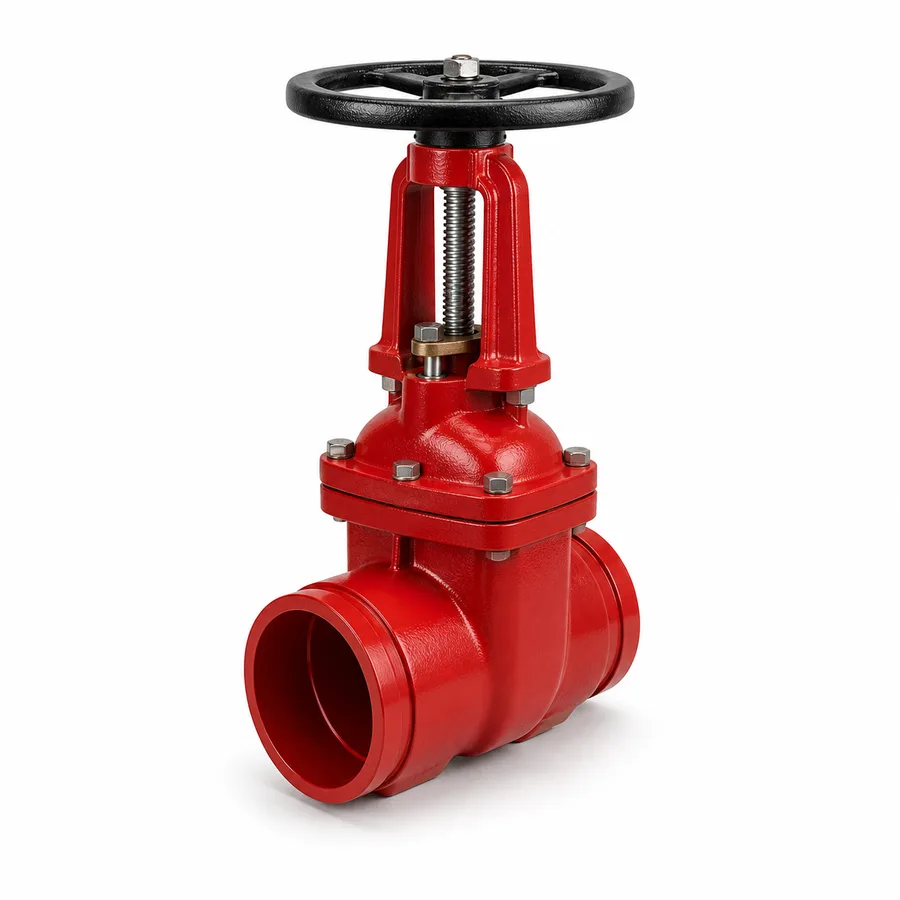
Outside screw and yoke (OS&Y) rising-stem gate valve from the TECTUL catalog in two references: the grooved OS&Y, UL 262 Listed and FM 1120 Approved for fire protection networks with a grooved coupling, and the ANSI 125 flanged rising-stem iron gate valve, for pump rooms and industry where visible position also matters without being a fire code valve. Both share the same mechanism — the stem rises visibly out of the body when opening, so position is verified at a glance — and this sheet is their common data sheet: why the code requires that visual verification and the electrical supervision of the tamper switch, what the UL/FM listings certify, working and test pressure, and the grooved end per AWWA C606.
Important: Before using these data in engineering, design or installation decisions on systems exposed to mechanical, pressure, rupture, fatigue, impact or water-hammer risk, it is essential to read the technical notice and limitation of liability at the end of this sheet.
SKU VT-valvula-compuerta-osy-ranurada · line of 2 references: UL/FM grooved OS&Y (fire) and ANSI 125 flanged (industrial)
1. Technical specifications
The two TECTUL catalog references
| Grooved OS&Y (fire) | Rising-Stem Flanged Iron Gate Valve (industrial) | |
|---|---|---|
| Service | Fire protection network, sprinkler pump room, grooved riser | Industrial networks, pump rooms, factory water services — no fire code requirement |
| Body | Ductile iron | Iron (lot grade — gray or ductile depending on manufacturer, confirmed on quotation) |
| Ends | Grooved for mechanical coupling, per AWWA C606 | Flanged, class 125 (ASME B16.1) |
| Standard / listing | UL 262 Listed · FM 1120 Approved · AWWA C515 reference construction | ANSI 125 (MSS SP-70, dual class 125 WSP / 200 WOG) — not a UL/FM listed product |
| Mechanism | Outside screw and yoke rising stem (OS&Y) | Outside screw and yoke rising stem (OS&Y) |
| Supervision | Prepared for a supervisory (tamper) switch wired to the fire panel | Not applicable — not a fire code valve |
Both references share the OS&Y mechanism (visible stem), which is what this sheet covers in common; they differ in end connection, listing and intended service. The exact iron grade of the flanged reference (gray or ductile) is manufacturer data and is confirmed on quotation.
Materials by component (fire reference, UL/FM)
| Component | Material | Designation / function |
|---|---|---|
| Body and yoke | Ductile iron | OS&Y structure exposed outside the body |
| Gate | EPDM-coated ductile iron | Resilient seat, AWWA C515-family pattern |
| Stem | Bronze or stainless steel | Acme thread exposed between the yoke and the handwheel — visible along its full travel |
| Coating | Fusion-bonded epoxy, AWWA C550 | Interior and exterior |
| Ends | Machined groove per AWWA C606 | For rigid or flexible coupling of the grooved line |
Regulatory framework
| Valve type | Rising-stem (OS&Y) gate valve, visible position indication |
| Grooved-end standard | AWWA C606 — Grooved and Shouldered Joints: groove dimensions and tolerances for ductile iron pipe DN 100–900 mm (4"–36") and steel/IPS pipe DN 19–600 mm (3/4"–24") |
| Fire listings | UL 262 (Gate Valves for Fire-Protection Service) and FM Class 1120/1130 — see section 2 |
| Flanged reference standard | ANSI/class 125 pattern, ASME B16.1 flanges |
| Usual sizes | 4" to 12" on the grooved fire reference (usual range for UL/FM grooved OS&Y); 2" to 12" on the industrial flanged reference |
| Service temperature | Up to 82 °C (180 °F) on the fire line, water without shock on the industrial one |
⚠ Important: this technical data sheet is a reference guide to the product's properties; it is not a quality certificate for the product you are buying. Heats vary from one another and may differ from the values stated here, or even depart from the standards. If your application requires compliance with a standard, always check the quality certificate (mill certificate) of the lot you are buying. If in doubt, ask one of our technical advisors →
2. Rating system: why the code requires visual indication and supervision
On a fire protection network the question that matters is not just "how much pressure does the valve take" but "is it open right now?" An automatic sprinkler only protects if water can reach it; if someone closed the isolation valve — by mistake, during construction, or for maintenance — and nobody notices, the whole system is disabled with no alarm to show it. That is why the fire protection code requires main control valves to have visible position indication (the OS&Y: the stem rises and can be seen from a distance whether it is open) and, in supervised installations, a flow or supervisory (tamper) switch that reports any unauthorized closing to the panel.
What UL 262 and FM 1120 certify
| UL 262 | Underwriters Laboratories standard for gate valves for fire-protection service: sets the design, material and test requirements the manufacturer must meet for its valve to be UL Listed for this application. |
| FM 1120/1130 | FM Approvals (FM Global) approval standard for gate valves: an independent acceptance criterion, with its own test protocol, for the valve to be FM Approved. |
| What they jointly certify | That that component — the valve, as it leaves the factory — meets the standard's design, material and pressure requirements. They do not certify the whole installed system nor replace the fire authority's or the project's insurer approval, which reviews the installation as a whole. |
Working and test pressure
| Datum | Value | Scope |
|---|---|---|
| Usual UL/FM rating of the line | 200 psi (13.8 bar) | This is the figure that governs for listing purposes — many UL/FM grooved OS&Y lines are certified at 200 psi even though the body, by its AWWA-family construction, could take more |
| Body design pressure (AWWA construction reference) | Up to 300 psi (20.7 bar) depending on the construction family | This is the body's capacity before the listing's limit is applied — it does not replace the certified figure |
| Factory hydrostatic test | Not less than 150 % of the certified working pressure | AWWA practice for the valve body, also required by the UL/FM listing protocol |
IMPORTANT
This data sheet is a reference guide to the properties of this product type. The measurements, dimensions and physical or geometric characteristics of the product actually supplied may vary by manufacturer and lot, and may even fall outside the cited standards. If any of these figures is critical to your design or build, it is essential to verify it with one of our advisors against the physical product, so you can be fully certain of what you are buying. · Original data sheet: tectul.com/en/conduccion-de-fluidos/valvulas/ficha-tecnica-valvula-compuerta-osy-ranurada.html
The figure that governs is always the certified product's UL/FM listing, not the body's theoretical capacity. When the project requires listed components, specify "200 psi UL/FM" rather than "300 psi design": these are two different figures and only the first has code-compliance value for the authority having jurisdiction. The exact listing of the reference (pressure, size, end type) is confirmed on quotation with the manufacturer's certificate.
3. OS&Y versus NRS: where each one goes
OS&Y (Outside Screw and Yoke) and NRS (Non-Rising Stem) are the two operating families of a gate valve, and the choice is not one of preference but of where the valve sits and who needs to see its position.
| OS&Y (rising stem) | NRS (non-rising stem) | |
|---|---|---|
| Stem movement | Rises and lowers visibly outside the body, through the outside yoke, as the nut turns on the stem itself | Rotates on its internal nut without traveling; no moving part visible outside the body |
| Position verification | At a glance, from any distance: the exposed stem shows whether it is open or closed | Not possible at a glance; requires turn logging, a locator or an auxiliary indicator |
| Where it is installed | Above floor level, indoors: pump rooms, machine rooms, sprinkler risers, industrial plants | Buried or in deep chambers, where the rising stem's vertical clearance does not fit |
| Code requirement | Mandatory where the fire code requires unambiguous visual position indication on main control valves | Not applicable to fire control valves requiring visual verification |
| Stem exposure | The stem is exposed to impact, atmospheric corrosion and needs clearance for its full travel | The non-rising stem needs no extra vertical clearance and is not exposed |
The practical rule is simple: if the code requires unambiguous position visibility, use OS&Y; if the valve is buried or in a deep chamber, use NRS — a buried OS&Y has nowhere for the stem to rise, and an NRS on a fire network does not meet the visual verification requirement. This catalog's companion sheet (AWWA C509/C515 resilient-seated gate valve) covers the NRS line for waterworks; this sheet covers the OS&Y line for fire protection and machine rooms.
4. Maintenance and periodic testing
A main fire control valve is not installed and forgotten: the fire protection systems maintenance code (NFPA 25) sets inspection and test frequencies that depend on whether the valve is supervised.
| Valve condition | Position inspection frequency |
|---|---|
| No lock, seal or electronic supervision | Weekly |
| Locked or mechanically sealed open | Monthly |
| Electronically supervised (flow/tamper switch to the panel) | Quarterly |
- Open the valve to the stop, traveling the stem's full range.
- Close it completely and verify the seal.
- Return it to the normal service position (open) and back off about a quarter turn from the fully open stop, a practice that prevents the mechanism from jamming at the end of travel.
- Grease the stem during this same operation, taking advantage of the thread being exposed and in motion.
This full operation test is also repeated every time the valve had to be closed for a repair or line intervention, not only on the annual cycle. The supervisory switch, where fitted, is checked together with the position: it must report any unauthorized closing to the panel before the valve completes its travel.
5. Frequently asked questions
Why does a fire protection valve need to show its position?
Because an automatic sprinkler only protects if water can reach it, and if the isolation valve was closed by mistake or during maintenance without anyone noticing, the whole system is disabled with no alarm to show it. That is why the code requires visual indication (OS&Y rising stem) and, in supervised installations, a switch that reports any unauthorized closing to the panel.
What does it mean for a valve to be UL Listed and FM Approved?
That component, as it leaves the factory, meets the design, material and test requirements of UL 262 (Underwriters Laboratories) and the FM 1120/1130 (FM Approvals) approval standard. It is the certification of the product, not of the whole installed system: approval of the installation belongs to the fire authority or the project's insurer.
What pressure does the valve take: 200 or 300 psi?
It depends on what the figure is being cited for. This line's usual UL/FM listing is 200 psi, and that is the figure that governs for code-compliance purposes when the project requires listed components. The body's construction, by its AWWA family, may take up to 300 psi of design pressure, but that figure does not replace the certified listing rating.
How is it different from a grooved or flanged check valve, or a valve without OS&Y?
The OS&Y is a shut-off valve with a visible stem; a grooved check valve, for example, prevents backflow and cannot manually isolate the network. Compared with the non-rising stem (NRS) gate valve in this catalog's companion sheet, the difference is visual position verification: the OS&Y offers it, the NRS does not, which is why NRS is used buried while OS&Y is used where the code requires seeing the position.
How often is an OS&Y fire network valve tested?
Position inspection is weekly if it has no lock, seal or electronic supervision; monthly if sealed or locked open; quarterly if electronically supervised to the panel (NFPA 25). It also gets a full operation test — opening and closing through its whole travel — at least once a year, and every time it is closed for a line repair.
What standard governs the grooved end?
AWWA C606, which sets the dimensions and tolerances of the machined groove for ductile iron and IPS-dimension steel pipe. The coupling — rigid or flexible — and its manufacturer are data confirmed on quotation according to the project's grooved system.
6. Application notes
Feasibility
The UL/FM grooved reference covers fire networks with a grooved riser where the project requires listed components and visual position verification, with a 200 psi listing rating. The ANSI 125 flanged reference covers industrial service and pump rooms where seeing the position matters without being a fire code valve. Neither is the choice for buried installation (use the NRS line in the companion sheet) nor for pressures or temperatures outside the listing range without checking against the manufacturer's certificate. For critical or life-safety applications, consult our technical team before specifying.
Installation
Install with grooved couplings compatible with the line's standard (AWWA C606), leaving the stem fully visible with its travel clear of walls, ducts or nearby fittings. Wire the supervisory switch to the fire panel before commissioning, if the project requires it. On the flanged reference, align the flanges and tighten the bolts in a cross pattern. Leave permanent access for position reading and inspection without removing neighboring equipment.
Design
Confirm with the network designer whether the project requires listed/approved components: that decides whether the UL/FM grooved reference is required or the ANSI 125 flanged one is sufficient. Specify size, the system's pressure class, a groove standard compatible with the couplings, and the need for a supervisory switch with its wiring. Plan for the stem's fully-open vertical clearance from the layout, not on site. The exact listing of the reference (certified pressure, size, end type) is confirmed on quotation with the manufacturer's certificate.
7. Technical notice and limitation of liability
The listings, pressures and dimensions in this sheet combine UL 262, FM 1120/1130, AWWA C606, AWWA C515 and MSS SP-70/ASME B16.1 with catalog evidence from manufacturers of OS&Y valves for fire protection and industrial service. The 200 psi UL/FM rating is the usual listing value for this product family; the exact certified listing of each reference (pressure, size, end type) is confirmed on quotation with the manufacturer's UL/FM certificate.
The inspection and test frequencies in section 4 summarize NFPA 25 practice for supervised and unsupervised main control valves; they do not replace the specific inspection, testing and maintenance program required by the authority having jurisdiction or the project's insurer. The ANSI 125 flanged reference is not a UL/FM listed product and must not be installed as a fire code component unless the manufacturer certifies otherwise.
These values must not be used as the sole criterion in life-safety applications, certified fire protection, or wherever valve failure may compromise people, property or the environment: in such cases the design and installation approval belong to the fire protection engineer and the project's authority having jurisdiction. Before deciding with these data, consult our technical team.
Sources
- UL 262 — Standard for Gate Valves for Fire-Protection Service: requisitos de diseño, materiales y ensayo para el listado UL de válvulas de compuerta contra incendio
- FM Approvals Class Number 1120/1130 — Approval Standard for Gate Valves: criterio de aprobación FM para válvulas de compuerta de servicio contra incendio
- AWWA C606 — Grooved and Shouldered Joints: dimensiones y tolerancias del extremo ranurado para tubería de hierro dúctil (DN 100–900 mm) y acero IPS (DN 19–600 mm)
- AWWA C515 — Reduced-Wall, Resilient-Seated Gate Valves for Water Supply Service: familia constructiva de referencia del cuerpo de la línea OS&Y ranurada
- AWWA C550 — Protective Interior Coatings for Valves and Hydrants: recubrimiento epóxico fusionado interior y exterior
- MSS SP-70 — Gray Iron Gate Valves, Flanged and Threaded Ends: sistema de clase dual 125 WSP / 200 WOG de la válvula de compuerta de hierro clase 125
- ASME B16.1 — Gray Iron Pipe Flanges and Flanged Fittings: patrón de perforación clase 125 de la referencia bridada
- NFPA 25 — Standard for the Inspection, Testing, and Maintenance of Water-Based Fire Protection Systems: frecuencias de inspección de válvulas de control (semanal/mensual/trimestral según supervisión) y prueba anual de operación completa
- Kennedy Valve Company / M&H Valve Company / Mueller Co. — submittals de válvulas de compuerta OS&Y ranuradas UL Listed / FM Approved: rating comercial habitual de 200 psi, evidencia de catálogo de fabricantes del estándar
This data sheet is the property of TECTUL, part of the Industrias IMR group. Reproduction without attribution is prohibited. Original document and updates: tectul.com/en/conduccion-de-fluidos/valvulas/ficha-tecnica-valvula-compuerta-osy-ranurada.html.