 TECTULby IMR
Plastic-body float valves: PVC lever type and automatic piston type
TECTUL · Dispatch across Colombia · Exports to Central & South America
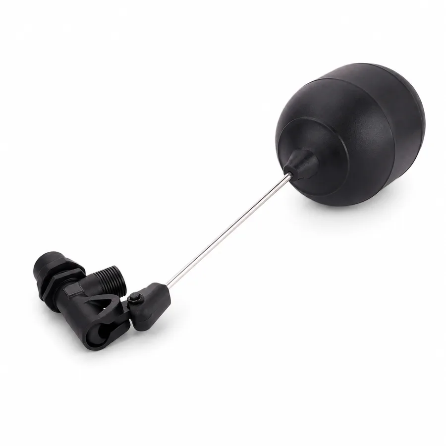
This sheet covers the two plastic-body float valves in the TECTUL catalog, which share material but not mechanism. The PVC float valve (1/2″ to 2″ NPT, 5 variants) is a classic lever valve with an external float; the automatic float valve, in food-grade PA66 nylon, is an internal-piston valve actuated by the line's own pressure, with a washable stainless filter and no external arm. That is why the first is described by a maximum pressure per float size and the second by a continuous working-pressure range. For the PVC line, this sheet publishes the most complete manufacturer data in the whole catalog float valve family: the survey of the LD-856A model with flow rates by pressure, maximum pressure per float size, materials per component and the complete dimensional table from drawing LD-85SA.
Important: Before using these data in engineering, design or installation decisions on systems exposed to mechanical, pressure, rupture, fatigue, impact or water-hammer risk, it is essential to read the technical notice and limitation of liability at the end of this sheet.
SKU VT-59214 (PVC float valve, 1/2″-2″ NPT, 5 variants) · plastic block of 2 references; the second is the automatic float valve in food-grade PA66 nylon, 1/2″ male BSP thread with DN25 port
1. Technical specifications: 2 plastic references and the LD-856A manufacturer data
The TECTUL catalog publishes two plastic-body float valves. They share the material's rationale —they do not corrode in water with chlorine, fertilizers or chlorides, where bronze and brass are attacked— but they do not share a mechanism, and therefore they do not share the way their capacity is declared (section 2). This family has no single international rating standard: each manufacturer declares its own.
1.1 Plastic-body references in the TECTUL catalog
| Reference | Material | Mechanism | Connection and sizes | Declared capacity figure |
|---|---|---|---|---|
| PVC float valve | PVC-U body; plastic float | Lever with external float | 1/2″ · 3/4″ · 1″ · 1-1/2″ · 2″ NPT (5) | See the LD-856A line manufacturer data (1.2): 100 psi with a 6″ float and 150 psi with an 8″ float |
| Automatic float valve | Food-grade PA66 nylon; washable stainless steel filter | Internal piston actuated by line pressure, no external arm | 1/2″ male BSP thread, DN25 port (1) | 1.5-150 psi (0.1-10 bar) continuous working pressure · 0-120 °C |
IMPORTANT
This data sheet is a reference guide to the properties of this product type. The measurements, dimensions and physical or geometric characteristics of the product actually supplied may vary by manufacturer and lot, and may even fall outside the cited standards. If any of these figures is critical to your design or build, it is essential to verify it with one of our advisors against the physical product, so you can be fully certain of what you are buying. · Original data sheet: tectul.com/en/conduccion-de-fluidos/valvulas/ficha-tecnica-valvula-flotador-pvc.html
The PVC float valve publishes 5 variants: there is no 1-1/4″ or 2-1/2″ in the active series. The 0-120 °C thermal range of the automatic float valve is catalog data from that product's manufacturer and corresponds to the PA66 compound; it does not apply to the PVC-U body of the first reference, whose ceiling is 60 °C (140 °F) like the rest of TECTUL's plastic catalog (FT-TC-VAL-PIE-PVC-001 and FT-TC-ACC-PVCP-001, not repeated here). Metal-body float valves (bronze, brass, stainless) and the kit spare parts are not in this sheet: they are in FT-TC-VAL-FLOTADORA-METAL-001.
1.2 Manufacturer data: PVC float valve, LD-856A line
In August 2026 TECTUL compiled the complete commercial data sheet for the PVC float valve from the manufacturer LD Pipe Fittings & Valves (Taiwan), model LD-856A, from the commercial catalog and the manufacturer drawing LD-85SA. It is the most complete performance data in the whole catalog float valve family and serves as the engineering reference for the «PVC float valve» line.
| Body and slider | PVC / reinforced thermoplastic |
| Seals and gaskets | EPDM and NBR |
| Hardware: bolt, nut, pin and rod | Stainless steel 304 / 316 |
| Float | Polyethylene (PE). 6″ standard; 8″ for the higher-pressure rating |
| Threaded rod | 8″, the same in both float configurations |
| LD-856 line connection | 1″ NPS; also available in NPT, BSPT and BSP on request |
| Flow rate at 30 psi (2.1 bar) | 47 GPM · 178 L/min |
| Flow rate at 60 psi (4.1 bar) | 61 GPM · 231 L/min |
| Maximum working pressure — 6″ float, 8″ rod | 100 psi · 6.9 bar |
| Maximum working pressure — 8″ float, 8″ rod | 150 psi · 10.3 bar |
IMPORTANT
This data sheet is a reference guide to the properties of this product type. The measurements, dimensions and physical or geometric characteristics of the product actually supplied may vary by manufacturer and lot, and may even fall outside the cited standards. If any of these figures is critical to your design or build, it is essential to verify it with one of our advisors against the physical product, so you can be fully certain of what you are buying. · Original data sheet: tectul.com/en/conduccion-de-fluidos/valvulas/ficha-tecnica-valvula-flotador-pvc.html
1.3 Dimensional table of the LD line (manufacturer drawing LD-85SA, mm)
| Size | Di | Do | Length L | Height H | S | W | Rod | Float |
|---|---|---|---|---|---|---|---|---|
| 1/2″ | 13 | 13 | 79.8 | 55.5 | 35 | 18 | 1/4″ × 8″ | 1/4″ × 5″ |
| 3/4″ | 19 | 18 | 90 | 55.5 | 35 | 19.2 | 1/4″ × 8″ | 1/4″ × 5″ |
| 1″ | 22 | 22 | 123 | 72.7 | 45 | 25.5 | 1/4″ × 10″ | 1/4″ × 6″ |
| 1-1/4″ | 31 | 33 | 175.6 | 90.6 | 55 | 38.1 | 5/16″ × 8″ | 5/16″ × 6″ |
| 1-1/2″ | 36 | 33 | 176 | 91 | 55 | 38.1 | 5/16″ × 8″ | 5/16″ × 8″ |
| 2″ | 47 | 47 | 207.9 | 125.9 | 75 | 50 | 5/16″ × 10″ | 5/16″ × 10″ |
| 2-1/2″ | 52 | 53 | 313 | 170.8 | 100.5 | 75 | 7/16″ × 10″ | 7/16″ × 10″ |
| 3″ | 65 | 66 | 314.5 | 172.3 | 100.5 | 75 | 7/16″ × 10″ | 7/16″ × 10″ |
IMPORTANT
This data sheet is a reference guide to the properties of this product type. The measurements, dimensions and physical or geometric characteristics of the product actually supplied may vary by manufacturer and lot, and may even fall outside the cited standards. If any of these figures is critical to your design or build, it is essential to verify it with one of our advisors against the physical product, so you can be fully certain of what you are buying. · Original data sheet: tectul.com/en/conduccion-de-fluidos/valvulas/ficha-tecnica-valvula-flotador-pvc.html
Dimensions in millimeters. Di and Do are the connection diameters, L the overall length, H the height, and S and W arm dimensions. Threads per size available in NPT and BSPT (for example 1″-NPT-11.5 and 1″-BSPT-11). The manufacturer drawing's table covers 1/2″ to 3″; the series published by TECTUL under «PVC float valve» runs 1/2″ to 2″ (5 variants) — the exact correspondence between each catalog variant and its drawing row is confirmed on quotation. Source: manufacturer drawing LD-85SA and commercial catalog LD-856A from LD Pipe Fittings & Valves, compiled by TECTUL in August 2026; these are manufacturer data, not independently tested by TECTUL.
⚠ Important: this technical data sheet is a reference guide to the product's properties; it is not a quality certificate for the product you are buying. Production lots vary from one another and may differ from the values stated here, or even depart from the standards. If your application requires compliance with a standard, always check the quality certificate (mill certificate) of the lot you are buying. If in doubt, ask one of our technical advisors →
2. Two different mechanisms under the same commercial name
The two references in this sheet are sold as «float valves», but they work in incompatible ways. Confusing them when specifying produces the block's most expensive error: asking for a pressure range where there is only a closing point, or expecting an external arm where there is none.
| PVC lever float valve | Automatic piston float valve | |
|---|---|---|
| How it closes | The external float rises with the water level and, by moment balance through the arm, pushes the plug against the seat | An internal piston actuated by the line's own pressure opens and closes the passage; there is no arm or float visible outside the body |
| What its capacity depends on | On the float size and arm length: they generate the closing force against the seat area | On the piston's internal hydraulic balance: the line provides the force, not a float |
| How the figure is declared | A maximum pressure point per configuration: 100 psi with a 6″ float or 150 psi with an 8″ float | A continuous working pressure range: 1.5 to 150 psi (0.1 to 10 bar) |
| Why that difference | Because the closing force is finite and fixed by the kit: there is a pressure above which the mechanism no longer overcomes the seat | Because the mechanism leans on line pressure: more pressure does not defeat it, it assists it. The lower limit (1.5 psi) exists because below that pressure the piston has nothing to operate with |
| Space and mounting | Needs free travel for the arm and float inside the tank | Compact, with no external travel; it incorporates a washable stainless filter at the inlet |
| Catalog connection | 1/2″ to 2″ NPT (5 variants) | 1/2″ male BSP thread, DN25 port (1 variant) |
| Declared temperature | Limited by PVC-U: 60 °C (140 °F) | 0 to 120 °C, manufacturer catalog data for the PA66 compound |
IMPORTANT
This data sheet is a reference guide to the properties of this product type. The measurements, dimensions and physical or geometric characteristics of the product actually supplied may vary by manufacturer and lot, and may even fall outside the cited standards. If any of these figures is critical to your design or build, it is essential to verify it with one of our advisors against the physical product, so you can be fully certain of what you are buying. · Original data sheet: tectul.com/en/conduccion-de-fluidos/valvulas/ficha-tecnica-valvula-flotador-pvc.html
When each one applies
The PVC lever float valve is the option when the tank has room for the arm and float, when the actuation level should be visible and adjustable by hand, and when the required size exceeds 1/2″. The automatic piston valve is the option when there is no room for an arm, when line pressure is highly variable (its 1.5 to 150 psi range covers everything from a gravity tank to a high-pressure line), when the water carries particles worth filtering before the seat —it has an integral washable stainless filter— and when the material requirement is food grade, which is what the PA66 nylon provides.
3. Enlarging the float raises the rating without touching the seat
3.1 The manufacturer figure that reveals the physics
The LD-856A data sheet publishes two ratings for the same valve: 100 psi with a 6″ float and 150 psi with an 8″ float. What is notable is what does not change between the two configurations: neither the connection size, nor the seat, nor the rod —8″ in both cases—. The manufacturer raises capacity by 50 % by enlarging the float alone.
The reason is a moment balance. In a lever float valve there are two opposing forces:
- The closing one: the float's buoyant thrust —proportional to its volume, and a sphere's volume grows with the cube of the diameter— multiplied by the lever arm ratio. Going from a 6″ float to an 8″ one multiplies the volume by about 2.4.
- The one to overcome: line pressure multiplied by the seat area, which grows with the square of the seat diameter.
Since the manufacturer leaves the seat untouched and only enlarges the float, the entire gain goes to the closing-force side. Hence the jump from 100 to 150 psi.
3.2 Confirmation from the other direction
The same physics is observed in reverse in the metal line documented in FT-TC-VAL-FLOTADORA-METAL-001: there the manufacturer Helbert, with the standard copper-ball kit, publishes 125 psi at 1/2″-3/4″, 150 psi at 1″-1-1/2″ (scaling the kit with the size) and stops publishing a figure from 2″ to 3″, where the seat is already too large for the standard float. One series raises the rating by enlarging the float; the other stops publishing it when the seat wins the race. These are two independent manufacturer catalogs behaving exactly as the moment balance predicts.
3.3 What to do with that when specifying
| Situation | What to do |
|---|---|
| The line runs below 100 psi (6.9 bar) | The 6″ float configuration is sufficient |
| The line runs between 100 and 150 psi (6.9 to 10.3 bar) | Specify the 8″ float configuration, checking that the tank has room for the larger float's travel |
| The line exceeds 150 psi (10.3 bar) | The lever float valve stops being the right mechanism: reduce pressure upstream or move to a hydraulic mechanism (the automatic piston valve in this sheet, or a level control valve with pilot float) |
| The valve closes and reopens on its own | Line pressure exceeds the installed assembly's closing capacity. Enlarging the float —not changing the body— is the first lever |
| The float or rod was swapped for another size | The rating changed: the published maximum pressure applies to the exact catalog float + rod combination, not to the body on its own |
The relationship between float size, arm length, seat area and closing pressure is a standard consequence of solid mechanics and fluid statics, illustrated here with two real manufacturer data series. It does not come from testing by TECTUL nor does it constitute a selection formula: an actual unit's performance depends on the exact assembly, the seal condition and the manufacturing lot.
4. Mounting, maintenance and distinction from toilet fill valves
4.1 Mounting the PVC lever float valve
- Horizontal, with the body passing through the tank wall above the maximum level and the arm inward. The discharge must sit above the water level, never submerged.
- Arm and float free throughout their travel: without rubbing the tank wall, other piping, the ladder or the body itself. A single point of contact leaves the closure incomplete and the valve dripping permanently. With the 8″ float configuration, verify the space before purchasing.
- Plastic thread: hand-tight plus 1 or 2 turns with a wrench, with PTFE tape or a PVC-compatible sealant. Over-tightening is the number-one cause of plastic thread failure. In a transition to metal, the plastic male always goes inside the metal female, never the reverse. Wrench on the body, never on the arm or the float.
- Rod-to-float and rod-to-arm joints: hand-tight only, per the LD line manufacturer's guide; they are not wrench-tightened.
- The closing level is adjusted by changing the float's position on the rod. Bear in mind that this geometry also defines the closing force (section 3): an aggressive adjustment can leave the valve unable to close against the line.
4.2 Mounting the automatic piston float valve
It is compact and requires no arm travel. It threads in by its 1/2″ male BSP end; the flow port is DN25. It comes with a washable stainless steel filter at the inlet: provide access for removing and cleaning it, because a clogged filter reduces flow and ultimately prevents the piston from operating. The BSP thread is not interchangeable with NPT without an adapter: verify before installing.
4.3 Maintenance and diagnosis
| Symptom | Probable cause | What to check |
|---|---|---|
| Continuous leak with the tank full (PVC lever type) | Plug seal (EPDM or NBR) worn or with embedded sediment | Dismantle and inspect the seal; it is the normal wear point. It is not a lack of closing force |
| The float stays at mid height and does not close | Punctured float full of water, or arm rubbing an obstruction | Remove the float and check for water inside; check the free travel |
| It closes and reopens on its own at full line pressure | Line pressure above the assembly's rating (100 psi with a 6″ float) | Compare the actual pressure against section 3; consider the 8″ float configuration (150 psi) |
| Low flow on the automatic piston valve | Clogged stainless filter | Remove and wash the filter; it is washable and reusable |
| The automatic valve does not operate on a gravity tank | Pressure below the 1.5 psi (0.1 bar) minimum | Check the available head: the piston needs line pressure to operate |
| PVC body cracked at the thread | Over-tightening during installation | Replace; it cannot be repaired. Reassemble hand-tight plus 1-2 turns |
4.4 Distinction: these are not domestic toilet fill valves
The two references in this sheet are for storage tanks, cisterns, reservoirs and industrial, agricultural and process applications, with 1/2″ to 2″ connections and bodies in PVC-U or PA66 nylon. Domestic toilet fill valves are a different category: a miniature internal float or sliding-cup mechanism, sized for a toilet tank, with a different connection, a different body and a different flow rate. They share the physical principle of float closing, but they are not interchangeable in application, size or catalog. Ordering one for the other is this category's most frequent purchasing error.
5. Frequently asked questions
How much flow does a PVC float valve deliver?
Per the LD-856A line manufacturer's catalog data: 47 GPM (178 L/min) at 30 psi and 61 GPM (231 L/min) at 60 psi. Flow rises with line pressure, it is not a single value: to size a tank's filling time you must start from the actual pressure available at the point.
How much pressure does the PVC float valve withstand?
It depends on the float size, not on the body: 100 psi (6.9 bar) with a 6″ float and 150 psi (10.3 bar) with an 8″ float, with the same 8″ rod and the same seat. If the line at the installation point runs above 100 psi, the applicable configuration is the 8″ float, first verifying that the tank has room for the larger float's travel.
Why does a larger float withstand more pressure?
Because the force closing the valve comes from the float's buoyant thrust —proportional to its volume, which grows with the cube of the diameter— multiplied by the lever arm ratio, while the force to overcome is pressure times the seat area. Enlarging the float without touching the seat sends the entire gain to the closing side. It is the same physics that explains, in reverse, why the bronze line manufacturer stops publishing a closing pressure from 2″ upward (FT-TC-VAL-FLOTADORA-METAL-001).
What is the difference between the PVC float valve and the «automatic» one?
They are different mechanisms. The PVC float valve closes by lever with an external float: hence its figure is a maximum pressure point per float configuration. The automatic one is an internal-piston valve actuated by the line's own pressure, with no visible arm or float: hence it publishes a continuous working pressure range (1.5 to 150 psi), comes in food-grade PA66 nylon, carries a washable stainless filter and is available only in 1/2″ BSP with a DN25 port.
Does the automatic float valve work on a gravity tank?
Only if at least 1.5 psi (0.1 bar) of pressure is available, roughly one meter of water column. Below that minimum the piston has nothing to operate with. If the system is pure gravity at low head, the right mechanism is the lever float valve, which does not depend on line pressure to close.
Does it work for a toilet tank?
No. These two references are for storage tanks, cisterns and industrial, agricultural or process applications, with 1/2″ to 2″ connections. Domestic toilet fill valves use a miniature internal float mechanism with a different body, connection and flow rate: they share the physical principle, not the application, and they are not interchangeable.
PVC or bronze for the tank float valve?
PVC when the water has tank chlorine, fertilizers or chlorides that attack copper alloys, and when weight matters. Bronze when the service is clean fresh water, permanent and mechanically demanding, and when a closing pressure backed by the manufacturer's table at sizes 1/2″ to 1-1/2″ is required (FT-TC-VAL-FLOTADORA-METAL-001). For potable water with a material requirement or the food industry, no copper alloy applies: the food-grade PA66 nylon of the automatic valve or a stainless body is required.
6. Application notes
Feasibility
The PVC lever float valve (1/2″ to 2″ NPT) is the option for tank level control where the water carries chlorine, fertilizers or chlorides that attack bronze and brass, and where there is room inside the tank for the arm and float travel. Its capacity is defined by the float size: 100 psi with a 6″ float and 150 psi with an 8″ float per the LD-856A line manufacturer data. Above 150 psi the direct lever stops being the right mechanism. The automatic float valve in food-grade PA66 nylon is the option when there is no room for an arm, when line pressure varies widely (it covers 1.5 to 150 psi), when the water carries particles worth filtering —it comes with a washable stainless filter— and when the material requirement is food grade; it is available only in 1/2″ BSP with a DN25 port. If the service is clean fresh water with mechanical demands and a closing pressure backed by a manufacturer's table is needed, the metal body of FT-TC-VAL-FLOTADORA-METAL-001 applies.
Installation
The PVC float valve is installed horizontally, with the body passing through the tank wall above the maximum level, the discharge above the water level and the arm and float free throughout their travel: a single point of contact leaves the closure incomplete. With the 8″ float configuration, verify the tank space before purchasing. Tighten the plastic thread hand-tight plus 1 or 2 turns with a wrench using PTFE tape or a PVC-compatible sealant; in a transition to metal, the plastic male always goes inside the metal female. Wrench on the body, never on the arm or float, and the rod-to-float and rod-to-arm joints are hand-tight only per the LD line manufacturer's guide. The automatic float valve threads in by its 1/2″ male BSP end —not interchangeable with NPT without an adapter— and needs planned access for removing and washing its stainless filter, which is the assembly's maintenance part.
Design
Do not size the float valve by connection diameter alone: check the actual line pressure at the installation point against the rating of the float configuration you will specify (100 psi with 6″, 150 psi with 8″), and the flow available at that pressure (47 GPM at 30 psi, 61 GPM at 60 psi) against the filling time the process requires. Swapping the float or rod for another size changes the rating: the published maximum pressure applies to the exact catalog combination. Also check the water temperature against the PVC-U ceiling (60 °C) on the lever reference; the 0-120 °C range belongs to the automatic valve's PA66 compound and does not transfer to PVC. If the line exceeds 150 psi, reduce pressure upstream or move to a hydraulic mechanism. Where the installation requires backflow protection toward the line, provide the corresponding backflow device or vacuum breaker, which is not part of these valves. None of these values replaces the project's hydraulic design under the code governing the installation.
7. Technical notice and limitation of liability
The flow rates, maximum pressures, materials and dimensions of the LD-856A line are data published by the manufacturer LD Pipe Fittings & Valves (commercial catalog LD-856A and drawing LD-85SA, compiled by TECTUL in August 2026), and the pressure and temperature range of the automatic float valve is catalog data from that product's manufacturer. The catalog sizes and materials are values declared by TECTUL from its own variant records (Jul-Aug 2026 list). This family has no single international rating standard. These data guide selection; they are not a certificate of conformity for any given unit nor independent testing by TECTUL.
The dimensional table of drawing LD-85SA covers 1/2″ to 3″, while the series published by TECTUL under «PVC float valve» runs 1/2″ to 2″ (5 variants): the exact correspondence between each catalog variant and its drawing row is confirmed on quotation, as is the float configuration (6″ or 8″) each unit is supplied with. The 0-120 °C thermal range corresponds to the automatic float valve's PA66 compound and does not apply to the PVC-U body, whose service ceiling is 60 °C (140 °F).
The relationship between float size, arm length, seat area and closing pressure set out in section 3 is a standard consequence of solid mechanics and fluid statics, illustrated with manufacturer data; it is not a TECTUL measurement nor a selection formula. These values must not be used as the sole criterion in critical or safety applications, nor wherever level-control failure may compromise people, property or the environment —tank overflow, contamination by backflow into the line, loss of supply to a process—: in such cases the design belongs to the project's responsible engineer. Before deciding with these data, consult our technical team.
Sources
- Catálogo comercial LD-856A y plano de fabricante LD-85SA — LD Pipe Fittings & Valves (Taiwán), válvula flotadora PVC: materiales por componente (cuerpo PVC, sellos EPDM y NBR, herrajes inoxidables 304/316, boya de polietileno), caudal 47 GPM a 30 psi y 61 GPM a 60 psi, presión máxima 100 psi con boya de 6″ y 150 psi con boya de 8″, y tabla dimensional completa de 1/2″ a 3″ en mm (levantado por TECTUL, agosto 2026)
- Ficha de catálogo del fabricante del producto — válvula de flotador automática de entrada superior: nylon PA66 grado alimenticio, pistón interno accionado por presión, filtro de acero inoxidable lavable, conexión 1/2″ rosca macho BSP, puerto DN25, presión de trabajo 1,5-150 psi (0,1-10 bar) y rango térmico 0-120 °C
- ASTM D1784 y ASTM D1785 — compuestos rígidos de PVC y tubería PVC Schedule 40/80: temperatura máxima de servicio del PVC-U de 60 °C (140 °F), aplicable al cuerpo de la referencia de palanca; la tabla de factores por temperatura está publicada en FT-TC-VAL-PIE-PVC-001 y FT-TC-ACC-PVCP-001 y no se repite aquí
- ASTM F1498 — Standard Specification for Taper Pipe Threads 60° for Thermoplastic Pipe and Fittings: geometría de la rosca cónica plástica y regla de apriete a mano más 1-2 vueltas de llave del cuerpo de PVC
- ASME B1.20.1 — Pipe Threads, General Purpose (Inch) e ISO 7-1 / BS 21 para rosca BSP y BSPT: base de la distinción entre la conexión NPT de la línea PVC y la conexión BSP macho de la flotadora automática, no intercambiables sin adaptador
- Principio de balance de momentos y empuje hidrostático sobre un flotador (mecánica de sólidos y estática de fluidos, literatura de ingeniería estándar) — base física de la relación entre tamaño de boya, longitud de barra, área de asiento y presión máxima de cierre expuesta en la sección 3
- Catálogo del fabricante Helbert y Cía (marca distribuida por TECTUL) — serie de datos independiente citada en la sección 3.2 como confirmación inversa de la misma física (125 psi en 1/2″-3/4″, 150 psi en 1″-1-1/2″, sin dato de 2″ a 3″); los datos completos de esa línea están en FT-TC-VAL-FLOTADORA-METAL-001 y no se repiten aquí
- data/etapas/etapa-1-conduccion-de-fluidos/curaduria.json y data/scraped/products/*.json del catálogo TECTUL — descripciones comerciales de las 2 referencias de cuerpo plástico de esta ficha (registro interno, jul-ago 2026)
This data sheet is the property of TECTUL, part of the Industrias IMR group. Reproduction without attribution is prohibited. Original document and updates: tectul.com/en/conduccion-de-fluidos/valvulas/ficha-tecnica-valvula-flotador-pvc.html.