 TECTULby IMR
Threaded bronze globe valves, ASTM B62 C83600 — throttling and dual SWP/WOG classes (MSS SP-80)
TECTUL · Dispatch across Colombia · Exports to Central & South America
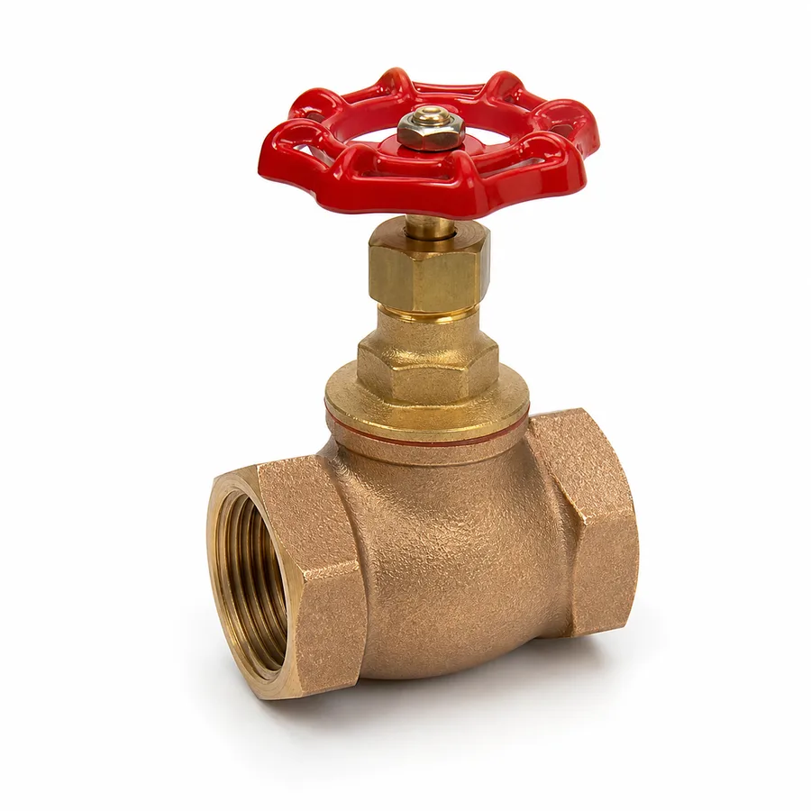
Two NPT threaded globe valve references in ASTM B62 C83600 cast bronze (85-5-5-5 alloy) from the TECTUL catalog, with a disc that seats axially on a seat located in the flow path, copper alloy stem and screw, ASTM B16 C36000 brass gland, asbestos-free PTFE packing and ASTM A536 ductile iron handwheel. Six published sizes per reference, 1/2″ to 2″ (DN 15 to DN 50), with the Napoli 330 line has 1 of 6 variants active and the Red White 125, 2 of 6. This sheet develops the one functional advantage that justifies its higher cost and higher pressure drop compared with a gate valve: a globe valve can throttle flow in a stable way.
Important: Before using these data in engineering, design or installation decisions on systems exposed to mechanical, pressure, rupture, fatigue, impact or water-hammer risk, it is essential to read the technical notice and limitation of liability at the end of this sheet.
SKU VT-104977 (Napoli 330 bronze globe valve) · 2 bronze globe references, 6 published sizes each from 1/2″ to 2″ with
1. Technical specifications
Materials by component
| Component | Material | Designation / standard |
|---|---|---|
| Body and bonnet | Cast bronze, 85-5-5-5 alloy (84–86 % Cu, 4–6 % Sn, 4–6 % Pb, 4–6 % Zn); globular chamber body with an internal web carrying the seat | ASTM B62, alloy C83600 |
| Closure member (disc) | Disc seating axially on the seat, guided by the stem; bronze or bronze disc holder with a soft insert depending on the figure | ASTM B62 C83600 (or disc holder + insert) |
| Seat | Metal-to-metal integral to the body, or PTFE soft seat where the manufacturer specifies it on the figure | Machined on the body / PTFE insert |
| Stem / screw | Bronze; high-strength brass on some figures | Copper alloy, manufacturer grade |
| Gland | Brass | ASTM B16, alloy C36000 |
| Stem packing | PTFE, asbestos-free | PTFE packing |
| Handwheel | Ductile iron with galvanized steel nut | ASTM A536 |
| Ends | Female tapered NPT thread on both ends | ASME B1.20.1 |
C83600 composition per ASTM B62. The seat type per figure (metal-to-metal or PTFE soft seat), the stem alloy grade and the bonnet-to-body joint are manufacturer data: confirmed on quotation or in the PDF sheet attached to the product.
Standards and service framework
| Design and rating standard | MSS SP-80 — Bronze Gate, Globe, Angle and Check Valves |
| Rating system | Dual SWP/WOG classes: 125, 150, 200 and 300 (see section 2) |
| Ends | Tapered NPT threads, ASME B1.20.1 |
| Closure member | Axial disc on a seat located in the flow path; the flow makes two 90° turns inside the body |
| Service function | Throttling and shutoff; it is the manual regulating valve of this family (see section 3) |
| Flow direction | It does have one: conventional arrangement with the fluid entering under the disc (see section 4) |
| Typical fluids | Cold and hot water, compressed air, non-corrosive oils and gases; saturated steam up to the class SWP |
| Practical thermal limit | The PTFE stem packing; with a PTFE soft seat, the seat insert as well |
Size equivalence
| Nominal | 1/2″ | 3/4″ | 1″ | 1-1/4″ | 1-1/2″ | 2″ |
|---|---|---|---|---|---|---|
| Metric DN | DN 15 | DN 20 | DN 25 | DN 32 | DN 40 | DN 50 |
IMPORTANT
This data sheet is a reference guide to the properties of this product type. The measurements, dimensions and physical or geometric characteristics of the product actually supplied may vary by manufacturer and lot, and may even fall outside the cited standards. If any of these figures is critical to your design or build, it is essential to verify it with one of our advisors against the physical product, so you can be fully certain of what you are buying. · Original data sheet: tectul.com/en/conduccion-de-fluidos/valvulas/ficha-tecnica-valvula-globo-bronce-napoli-330.html
Bronze globe references in the TECTUL catalog
| Reference | Published sizes |
|---|---|
| Napoli 330 bronze globe valve (SKU VT-104977) | 1/2″ · 3/4″ · 1″ · 1-1/4″ · 1-1/2″ · 2″ (6 sizes) |
| Red White 125 bronze globe valve | 1/2″ · 3/4″ · 1″ · 1-1/4″ · 1-1/2″ · 2″ (6 sizes) |
IMPORTANT
This data sheet is a reference guide to the properties of this product type. The measurements, dimensions and physical or geometric characteristics of the product actually supplied may vary by manufacturer and lot, and may even fall outside the cited standards. If any of these figures is critical to your design or build, it is essential to verify it with one of our advisors against the physical product, so you can be fully certain of what you are buying. · Original data sheet: tectul.com/en/conduccion-de-fluidos/valvulas/ficha-tecnica-valvula-globo-bronce-napoli-330.html
The numbers accompanying the commercial name (330 and 125) are manufacturer figure designations and must not be read as MSS SP-80 classes without confirming against the factory sheet. Face-to-face dimensions, height and weight by size are not standardized by MSS SP-80 for threaded bronze valves and are confirmed on quotation.
⚠ Important: this technical data sheet is a reference guide to the product's properties; it is not a quality certificate for the product you are buying. Heats vary from one another and may differ from the values stated here, or even depart from the standards. If your application requires compliance with a standard, always check the quality certificate (mill certificate) of the lot you are buying. If in doubt, ask one of our technical advisors →
2. MSS SP-80 dual classes: how to read the pressure of a bronze globe valve
Like the gate and angle valves, the bronze globe valve is rated under MSS SP-80 (Bronze Gate, Globe, Angle and Check Valves) with dual classes: each class carries an SWP (Saturated Working Pressure, allowable pressure on saturated steam) and a WOG (Water-Oil-Gas, allowable cold non-shock pressure). The two figures are paired and rise together.
| MSS SP-80 class | SWP — saturated steam | Saturation temperature at that SWP¹ | WOG — cold, ≤38 °C |
|---|---|---|---|
| 125 | 125 psig (8.6 bar) | ≈178 °C (353 °F) | 200 psi (13.8 bar) |
| 150 | 150 psig (10.3 bar) | ≈186 °C (366 °F) | 300 psi (20.7 bar) |
| 200 | 200 psig (13.8 bar) | ≈198 °C (388 °F) | 400 psi (27.6 bar) |
| 300 | 300 psig (20.7 bar) | ≈216 °C (421 °F) | 600 psi (41.4 bar) |
IMPORTANT
This data sheet is a reference guide to the properties of this product type. The measurements, dimensions and physical or geometric characteristics of the product actually supplied may vary by manufacturer and lot, and may even fall outside the cited standards. If any of these figures is critical to your design or build, it is essential to verify it with one of our advisors against the physical product, so you can be fully certain of what you are buying. · Original data sheet: tectul.com/en/conduccion-de-fluidos/valvulas/ficha-tecnica-valvula-globo-bronce-napoli-330.html
¹ Saturation temperature of steam at the stated SWP: it is a thermodynamic property of water, not of the valve. It is the same reference value ASME B16.3-2021 (Table 3-1, note 1) uses for the 186 °C limit of class 150 threaded fittings. WOG/CWP is the maximum cold non-shock pressure (−29 °C to 38 °C); it is not an ASME B16.34 class — the WOG figure is declared by the manufacturer per MSS SP-80.
The two reading rules
Rule 1 — the WOG only applies cold. The 200, 300, 400 or 600 psi in the catalog apply up to 38 °C (100 °F). On steam, the limit is set by the SWP of the same class: a "300 WOG" globe valve is also a "150 SWP" valve and at 186 °C it takes 150 psig of steam, not 300 psi.
Rule 2 — SWP and WOG are paired. The SWP of one class is never combined with the WOG of another. If the supplier only declares the WOG, the class is determined: 200 WOG → Class 125; 300 WOG → Class 150; 400 WOG → Class 200; 600 WOG → Class 300.
The third rule, specific to globe valves: the throttling ΔP is not the rating ΔP
In a gate valve, which works only open or closed, the relevant pressure is the line pressure. In a globe valve that throttles permanently, the critical element is the pressure drop across the seat with the valve partially open. SWP and WOG limit the pressure the body contains, not the differential the seat can sustain continuously without eroding or cavitating. A Class 125 valve installed on a 60 psi line can be perfectly within rating and still destroy its seat if it is left throttling a high ΔP for months. The allowable continuous throttling differential is manufacturer data and is confirmed on quotation.
- Service: low-pressure saturated steam at 90 psig, with a globe valve to trim the supply to a heat exchanger.
- Fluid temperature: at 90 psig (104.7 psia) saturated steam sits at ≈166 °C. Far above the 38 °C of the WOG, so the WOG does not apply: the SWP governs.
- Minimum class: Class 125 allows 125 psig SWP > 90 psig → it complies. That same valve will be marked "200 WOG" on the body, a figure that is irrelevant here.
- Seat check: at 166 °C a PTFE soft seat is ruled out for permanent service; a metal-to-metal seat applies (see section 4).
- Throttling check: if the valve is to be operated habitually near closed, the manufacturer must be asked for the allowable continuous seat ΔP — the SWP does not answer that question.
What the TECTUL catalog publishes. For the two bronze globe references in this sheet (Napoli 330 and Red White 125) the manufacturer does not publish the class number on the product page, and the numbers 330 and 125 in the commercial name are figure designations: they must not be interpreted as classes. The value is confirmed on quotation against the factory certificate or PDF sheet. As a family reference, the stainless globe line in the same catalog does declare 200 WOG (Class 125 → 125 psig SWP at ≈178 °C).
3. A globe valve does throttle: what it gains and what it costs
Globe geometry is exactly the opposite of gate geometry. Instead of a wedge that withdraws from the bore, a globe valve forces the fluid to rise into a chamber, cross a horizontal orifice — the seat — and descend again. A disc rests on that orifice and moves up or down with the stem. The disc motion is parallel to the orifice axis, not perpendicular to the flow.
Why that geometry allows regulation
- The flow area varies progressively and controllably. The effective area is the lateral surface of a cylinder whose height is the disc-to-seat gap: it grows smoothly with stem travel, so there is a wide, stable working band in which the operator can set the flow. In a gate valve, almost all the flow change is concentrated in a short stretch of the travel.
- The disc is guided and backed. Unlike the hanging wedge of a gate valve, the globe disc stays guided by the stem with the fluid thrust along a defined axis: it does not chatter in intermediate positions.
- Wear occurs where it should. The throttling jet strikes guiding surfaces and the disc, not the edge of the sealing surface as in the wire drawing of a gate valve. The valve tolerates working partially open for long periods.
- Travel is short. A displacement on the order of a quarter of the seat diameter is enough to go from closed to fully open, which makes operation quick and precise compared with the full travel of a gate valve.
The cost: pressure drop
The two 90° turns and the restriction at the seat make the globe valve a significant resistance even when fully open. Using the resistance coefficient model of Crane TP-410, a fully open globe valve is represented by K = 340·fT, against K = 8·fT for an open gate valve of the same size: roughly 42 times more resistance (fT is the fully turbulent friction factor of pipe of that size).
- 1″ (DN 25) steel line, water at 2.0 m/s. Velocity head:
v²/2g = 2.0² / (2 × 9.81) = 0.204 m. - Fully turbulent friction factor for 1″ commercial steel:
fT ≈ 0.023(Crane TP-410 table). - Fully open globe valve:
K = 340 × 0.023 = 7.82→ lossh = K·v²/2g = 7.82 × 0.204 = 1.60 mof water column (≈0.16 bar). - Fully open gate valve, same size:
K = 8 × 0.023 = 0.184→ lossh = 0.184 × 0.204 = 0.038 m(≈3.8 cm). - Reading: the globe valve costs about 1.56 m of extra pumping head per valve installed, even wide open. That is the trade-off of being able to regulate, and it is why globe valves are installed only where regulation is genuinely needed; every other point on the line takes a gate valve.
The two limits of throttling
Cavitation with liquids. When throttling, the local pressure at the vena contracta of the seat falls far below the downstream pressure. If that local pressure drops below the vapour pressure of the liquid at service temperature, bubbles form and implode as pressure recovers: that is cavitation. It sounds like gravel and erodes the seat and disc within weeks. It is avoided by staging the ΔP, raising the downstream pressure, or using a control valve designed for the service.
Erosion with steam and gases. With wet steam or particle-laden gases, the high-velocity jet through a small opening erodes the seat by impact. For permanent steam throttling it is advisable to oversize the valve so it works further open, or to move to a pressure-reducing valve.
The coefficients K = 340·fT (open globe) and K = 8·fT (open gate) are reference values from the Crane Technical Paper No. 410 method for fully open valves; the actual value of each figure depends on the manufacturer's internal design. If pressure drop is critical to the design, it must be verified against the Cv or K published by the manufacturer of the specific reference.
4. Soft or metal-to-metal seat, and flow under the disc
The two seat types
| Aspect | Soft seat (PTFE insert) | Metal-to-metal seat (bronze against bronze) |
|---|---|---|
| Shutoff tightness | Very high: PTFE deforms and copies seat irregularities; it tolerates small particles without losing the seal | Depends on the lapping of the faces; a scratch or a trapped particle produces a drip |
| Closing torque at the handwheel | Low: the seal is achieved by deforming the insert, not by crushing metal against metal | High: it requires pressing the disc onto the seat hard enough to elastically deform the faces |
| Maximum temperature | Limited by the PTFE, which loses mechanical properties long before the bronze does | Limited by the bronze and by the stem packing; it is the option for steam and hot services |
| Tolerance to abrasive solids | Lower: hard particles embed in the PTFE and then score the metal seat | Higher, although jet erosion still exists under heavy throttling |
| Repairability | The insert is replaced; it requires the manufacturer's spare | The seat can be refaced and the disc lapped in a workshop |
| Typical use | Cold and warm water, compressed air, services where tight shutoff and low operating effort matter | Saturated steam, condensate, hot oils, medium and high temperature services |
The seat type of each catalog figure (metal-to-metal integral to the body or PTFE soft seat) is manufacturer data: confirmed on quotation or in the factory PDF sheet. The selection rule is simple: if there is steam or medium-high temperature, metal-to-metal seat; if tight shutoff and low torque in cold services are the priority, soft seat.
Flow direction: why a globe valve has one
Unlike a gate valve, a globe valve is not symmetrical: the seat is mounted on an internal web and the disc approaches it from one particular face. The conventional arrangement takes the fluid under the disc, so line pressure pushes the disc in the opening direction (flow-to-open).
| Arrangement | How it works | Advantage | Trade-off |
|---|---|---|---|
| Flow under the disc (conventional) | Upstream pressure acts under the disc and tends to lift it | With the valve closed, the bonnet and stem packing sit on the depressurized side: less demand on the gland at rest and the option to service the packing with the valve closed and the line isolated | Greater handwheel effort to open against line pressure, especially in larger sizes and at high ΔP |
| Flow over the disc | Upstream pressure acts on the disc and presses it onto the seat | Lower opening effort and greater disc stability at very small openings; used in some high pressure and temperature steam services | With the valve closed, the bonnet and packing stay permanently pressurized |
Field rule: always respect the manufacturer's marking. If the body carries a flow-direction arrow, follow it without discussion; if it does not, identify the seat arrangement before mounting. Reversing a globe valve designed for flow under the disc subjects the packing to permanent pressure, can cause disc vibration at small openings and, in high-ΔP services, punishes the seat. The flow direction of each figure is confirmed in the factory PDF sheet or on quotation.
Installation and operation
- Thread. NPT seals by tapered metal-to-metal interference (ASME B1.20.1); PTFE tape or paste fills the helices and lubricates the make-up. Apply it on the male thread, never on the female, and without intruding into the bore.
- Tightening. Hold by the body with a wrench on the hexagonal end flats; never by the handwheel or the bonnet.
- Orientation. Preferably with the stem vertical and upward. On steam lines, avoid mounting with the stem downward: condensate collects in the bonnet and punishes the packing.
- Operation. Open and close slowly, particularly on liquids, so as not to generate water hammer by changing the flow abruptly. When closing, tighten only enough to seal; forcing the handwheel onto a metal-to-metal seat deforms the disc.
- Permanent throttling. Avoid operating steadily at very small openings: that is where jet velocity peaks and where cavitation and erosion appear. If the working point always sits near closure, the valve is oversized.
- Maintenance. A drip at the stem is corrected by gradually tightening the gland; that is normal maintenance. A drip through the seat with the valve closed indicates disc or seat wear, not packing wear.
5. Frequently asked questions
What is the real difference between a globe valve and a gate valve?
The gate valve is a full-shutoff device: fully open it leaves an almost full bore and loses very little pressure, but at partial opening the seat erodes and the wedge vibrates. The globe valve does throttle stably, because the disc is guided and the flow area varies smoothly with travel; in exchange, even fully open it loses roughly 42 times more pressure than a gate valve of the same size. Install gate valves at block points and globe valves only where regulation is required.
Is a bronze globe valve suitable for steam?
Yes, up to the SWP of its MSS SP-80 class. A figure that takes 300 WOG cold is Class 150 and carries saturated steam up to 150 psig, whose temperature is ≈186 °C. For steam it must have a metal-to-metal seat, not a PTFE soft seat. The exact class of the catalog's Napoli 330 and Red White 125 references is not published by the manufacturer and is confirmed on quotation.
Are the "330" and "125" in the name the pressure class?
Not necessarily: they are manufacturer figure designations. They must not be read as MSS SP-80 classes without confirming against the factory PDF sheet or on quotation; assuming so can lead to installing a valve below the service pressure.
How much pressure do I lose by installing a globe valve?
Considerably more than usually estimated. Using the Crane TP-410 method, an open globe valve is equivalent to K = 340·fT: on a 1″ line with water at 2.0 m/s that is about 1.60 m of water column (≈0.16 bar) per valve, against 0.038 m for a gate valve of the same size. In systems with several globe valves that loss accumulates and must enter the pump calculation.
Can I leave the globe valve almost closed permanently?
That is the operating mode that punishes it most. At very small openings jet velocity peaks: with liquids cavitation appears — a gravel-like noise and seat erosion within weeks — and with steam or gases, impact erosion. If the working point always sits near closure, the valve is oversized and it is advisable to drop a size or move to a regulating valve.
Which way round is it installed?
A globe valve does have a flow direction. The conventional arrangement takes the fluid under the disc, so that with the valve closed the stem packing is depressurized. If the body carries an arrow, follow it without exception; if it does not, identify the seat arrangement before mounting. The direction of each figure is confirmed in the factory sheet.
6. Application notes
Feasibility
The ASTM B62 C83600 bronze globe valve is the manual regulating option of this family: cold and hot water, compressed air, non-corrosive oils and gases, and saturated steam within the class SWP with a metal-to-metal seat. It is not the right valve for pure blocking duty — a gate valve costs less and loses 42 times less pressure — nor for permanent throttling at high ΔP, where a control or pressure-reducing valve applies. With chlorides, brines, process chemicals, ammoniacal compounds or a coastal environment, the choice is the CF8M stainless globe valve, which has its own data sheet.
Installation
A globe valve has a flow direction: the conventional arrangement takes the fluid under the disc, so that with the valve closed the bonnet and packing are depressurized. Respect the arrow cast on the body or identify the seat arrangement before mounting. The NPT thread (ASME B1.20.1) seals by tapered metal-to-metal interference; apply PTFE tape or paste on the male thread, never on the female, and tighten with a wrench on the hexagonal body flats, never by the handwheel or the bonnet. Prefer the stem vertical and upward; on steam, avoid mounting with the stem downward because condensate collects in the bonnet. Operate slowly so as not to induce water hammer, and do not force the handwheel when closing onto a metal-to-metal seat.
Design
The SWP/WOG ratings in section 2 apply to the valve under non-shock conditions and limit the pressure the body contains, not the differential the seat can throttle continuously: that figure is manufacturer data and must be requested when the valve is to operate permanently partially open. Water hammer, piping loads and moments, and start-stop transients belong to the project's design code (ASME B31.1, B31.3 or the applicable one). On liquids, check the cavitation margin by comparing the downstream pressure with the vapour pressure of the fluid at service temperature. In the hydraulic calculation, account for the globe valve loss with its actual K or Cv: underestimating it is a frequent error when sizing pumps. If the seat is a PTFE soft seat, the thermal ceiling of the valve is set by the insert, not by the bronze.
7. Technical notice and limitation of liability
The materials and sizes in this sheet come from the data TECTUL publishes on each product page (August 2026) and the rating framework comes from MSS SP-80 (dual SWP/WOG classes). The manufacturer does not publish the class number for the Napoli 330 and Red White 125 references: the numbers 330 and 125 are figure designations and must not be read as classes. The value is confirmed on quotation against the factory certificate or PDF sheet.
Face-to-face dimensions, overall height and weight by size are not fixed by a single standard for threaded bronze valves. The resistance coefficients quoted (K = 340·fT for an open globe valve, K = 8·fT for an open gate valve) are reference values from the Crane TP-410 method for fully open valves; the allowable continuous throttling ΔP of the seat is a different figure, specific to the manufacturer, and cannot be derived from the SWP or the WOG.
These values must not be used as the sole criterion in critical, safety or fire-protection applications, or wherever valve failure may compromise people, property or the environment: in such cases the design belongs to the project's responsible engineer under the applicable code (ASME B31.1/B31.3 for process piping), with the design temperature, the cavitation analysis and the load cases of the actual service. Before deciding with these data, consult our technical team.
Sources
- MSS SP-80 — Bronze Gate, Globe, Angle and Check Valves (sistema de clases duales SWP/WOG 125/150/200/300; alcance y clases confirmados vía GlobalSpec y catálogo técnico WALWORTH Industrial Bronze Valves 2017, que declara diseño conforme a MSS SP-80 para estas mismas clases)
- ASTM B62 — Standard Specification for Composition Bronze or Ounce Metal Castings, aleación C83600 (84–86 % Cu, 4–6 % Sn, 4–6 % Pb, 4–6 % Zn) — cuerpo, bonete y disco
- ASTM B16/B16M — Standard Specification for Free-Cutting Brass Rod, Bar and Shapes, aleación C36000 — prensaestopas
- ASTM A536 — Standard Specification for Ductile Iron Castings — volante
- ASME B1.20.1 — Pipe Threads, General Purpose, Inch (roscas NPT cónicas de los extremos)
- ASME B16.3-2021, Tabla 3-1, nota (1) — referencia de la temperatura de vapor saturado a 150 psig (186 °C), consistente con la ficha FT-TC-ACC-MALL-001 del catálogo
- Tablas de vapor saturado (propiedad termodinámica agua/vapor, fuente tipo NIST/ASME Steam Tables) — temperaturas de saturación a 90/125/150/200/300 psig
- Crane Co., Technical Paper No. 410 — Flow of Fluids Through Valves, Fittings and Pipe: coeficientes de resistencia de válvulas totalmente abiertas (globo K = 340·fT, compuerta K = 8·fT), factores de fricción fT en régimen totalmente turbulento por diámetro y método de cálculo de pérdida por carga de velocidad
- WALWORTH Industrial Bronze Valves Catalog (2017) — confirmación de materiales por componente (bronce B62 C83600, latón B16 C36000, hierro dúctil A536) y de la presencia de figuras de globo con asiento blando de PTFE y con asiento metal-metal (datos de fabricante, no de norma)
- Fichas de producto TECTUL (tectul.com): Válvula Globo Bronce Napoli 330 (SKU VT-104977) y Válvula Globo Bronce Red White 125 — diámetros publicados; y Válvula Globo Inoxidable 200 Psi como referencia del rating declarado en la familia
- Curaduría interna TECTUL (data/etapas/etapa-1-conduccion-de-fluidos/curaduria.json) — diámetros por referencia, agosto 2026
This data sheet is the property of TECTUL, part of the Industrias IMR group. Reproduction without attribution is prohibited. Original document and updates: tectul.com/en/conduccion-de-fluidos/valvulas/ficha-tecnica-valvula-globo-bronce-napoli-330.html.