 TECTULby IMR
Direct-acting water pressure reducing valves, threaded — 1/2″ to 2″, spring-loaded diaphragm or membrane, standard, angle and light-duty lines
TECTUL · Dispatch across Colombia · Exports to Central & South America
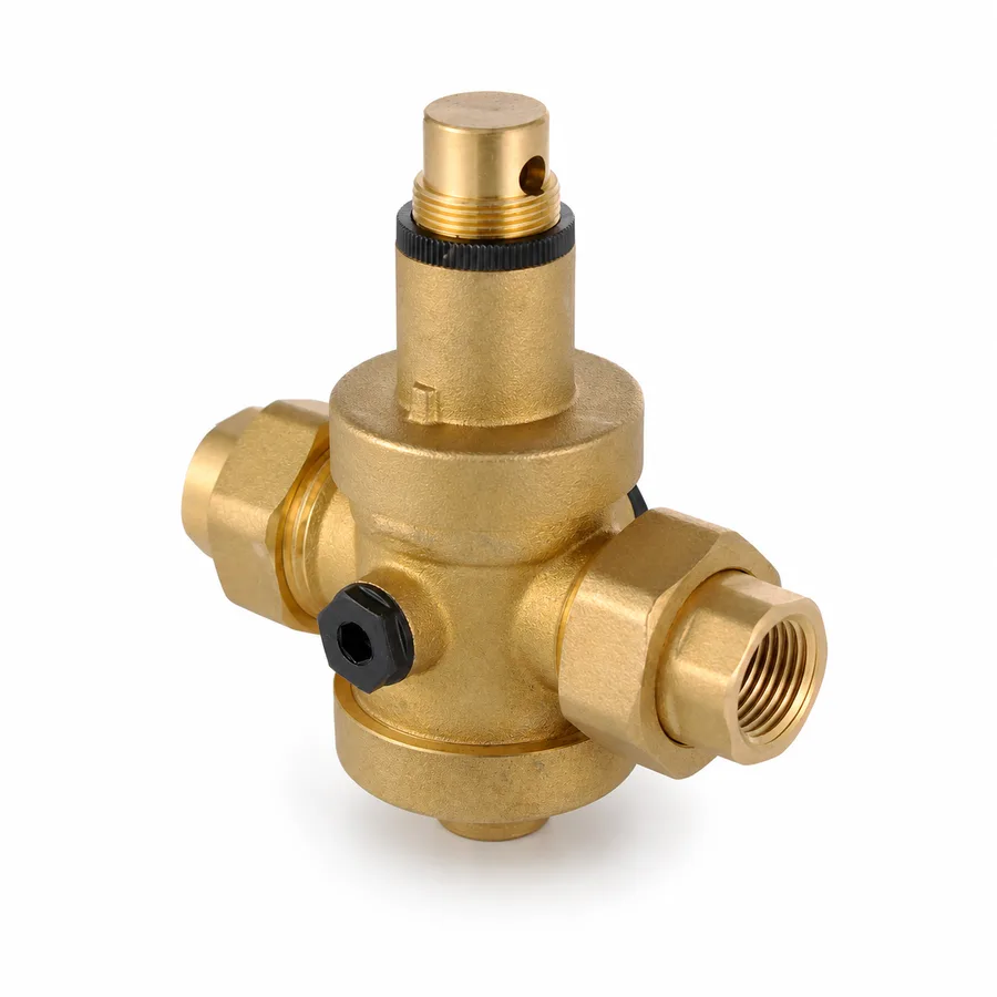
The three direct-acting water pressure reducing valves in the TECTUL catalog: 7 to 90 Lb Water Pressure Regulator (bronze-brass body, internal diaphragm), Angle Pattern Pressure Reducer (chrome-plated brass body, integral stainless strainer, 232 psi/16 bar inlet) and Light-Duty Water Pressure Regulator (bronze-brass, 22-85 psi adjustment range). All three are direct-acting: a spring-loaded diaphragm, self-contained, with no external pilot. The datum no commercial sheet explains: regulated pressure falls as flow increases — the fall-off effect — so the correct valve size is set by the design flow rate at an acceptable pressure drop, not by the pipe diameter it is mounted on. This sheet also publishes the EN 1567/ASSE 1003 framework, installation with strainer and gauge, why a hot-water circuit needs thermal expansion when the reducer acts as a check valve, and the two-stages-in-series rule when the reduction ratio is high.
Important: Before using these data in engineering, design or installation decisions on systems exposed to mechanical, pressure, rupture, fatigue, impact or water-hammer risk, it is essential to read the technical notice and limitation of liability at the end of this sheet.
SKU VT-87051 (7 to 90 Lb water pressure regulator) · line of 3 direct-acting water pressure reducing valve references, NPT threaded, from 1/2″ to 2″
1. Technical specifications
TECTUL catalog references and materials
| Reference | Body and components | Connection | Sizes offered |
|---|---|---|---|
| 7 to 90 Lb Water Pressure Regulator | Bronze-brass body; internal spring-loaded regulating diaphragm | Female NPT thread | 1/2″ · 3/4″ · 1″ · 1-1/2″ · 2″ |
| Angle Pattern Pressure Reducer | Chrome-plated brass body; NBR diaphragm and gaskets; nylon cap; integral stainless steel inlet strainer | NPT thread 1/2″ and 3/4″ | 1/2″ · 3/4″ · 1″ |
| Light-Duty Water Pressure Regulator | Bronze-brass body; reinforced rubber diaphragm | Female NPT thread | 1/2″ · 3/4″ · 1″ · 2″ |
IMPORTANT
This data sheet is a reference guide to the properties of this product type. The measurements, dimensions and physical or geometric characteristics of the product actually supplied may vary by manufacturer and lot, and may even fall outside the cited standards. If any of these figures is critical to your design or build, it is essential to verify it with one of our advisors against the physical product, so you can be fully certain of what you are buying. · Original data sheet: tectul.com/en/conduccion-de-fluidos/valvulas/ficha-tecnica-valvula-reguladora-de-agua-7-a-90l.html
All three references are direct-acting pressure reducing valves: an adjustable spring-loaded diaphragm or membrane, self-contained, with no external pilot or auxiliary power source. An adjustment screw on the cap compresses or releases the spring to raise or lower the target outlet pressure. None of the three carries an integral relief bypass or acts as an isolation valve: they are installed with their own shut-off valves upstream and downstream (section 3).
Regulatory framework and supply conditions
| Valve type | Direct-acting water pressure reducing/regulating valve: single spring-loaded diaphragm, self-contained |
| Reference standards | ASSE 1003 (self-contained, direct-acting, single-diaphragm devices for potable water distribution systems) and EN 1567 (water pressure reducing valves and combination valves for building installations) |
| EN 1567 dimensional scope | DN 8 to DN 100; inlet pressure up to 1.6 MPa (16 bar / 232 psi) |
| ASSE 1003 reference temperature | 0.6 °C to 60 °C (33 °F to 140 °F), minimum design |
| EN 1567 reference temperature | cold water ≤30 °C · hot water ≤80 °C |
| Ends | Female NPT thread per ASME B1.20.1 |
| Mounting position | Unless the manufacturer states otherwise, any orientation is the general EN 1567 criterion; keep the adjustment screw accessible and the gauge visible |
| Usual fluids | Potable water, industrial water and neutral liquids compatible with bronze-brass |
IMPORTANT
This data sheet is a reference guide to the properties of this product type. The measurements, dimensions and physical or geometric characteristics of the product actually supplied may vary by manufacturer and lot, and may even fall outside the cited standards. If any of these figures is critical to your design or build, it is essential to verify it with one of our advisors against the physical product, so you can be fully certain of what you are buying. · Original data sheet: tectul.com/en/conduccion-de-fluidos/valvulas/ficha-tecnica-valvula-reguladora-de-agua-7-a-90l.html
Pressure and adjustment range per reference
| Reference | Declared maximum inlet pressure | Outlet adjustment range | Service temperature |
|---|---|---|---|
| 7 to 90 Lb Regulator | Not published by the manufacturer for this reference; confirmed on quotation | 7 to 90 psi (0.5 to 6.2 bar), per the factory commercial name | Not published; the manufacturer refers to the PDF sheet attached to the product |
| Angle Pattern Reducer | 232 psi (16 bar) — matches the EN 1567 scope ceiling (1.6 MPa) for cold water | No independent adjustment range published beyond the factory set point; confirmed on quotation | Up to 60 °C |
| Light-Duty Regulator | Not published; confirmed on quotation | 22 to 85 psi (1.5 to 5.9 bar) | 0 °C to 80 °C |
IMPORTANT
This data sheet is a reference guide to the properties of this product type. The measurements, dimensions and physical or geometric characteristics of the product actually supplied may vary by manufacturer and lot, and may even fall outside the cited standards. If any of these figures is critical to your design or build, it is essential to verify it with one of our advisors against the physical product, so you can be fully certain of what you are buying. · Original data sheet: tectul.com/en/conduccion-de-fluidos/valvulas/ficha-tecnica-valvula-reguladora-de-agua-7-a-90l.html
The inlet pressure, adjustment range and temperature values are manufacturer catalog data for each reference, not an independent TECTUL test. Where the manufacturer does not publish a datum, the cell states so explicitly rather than being filled with another reference's value or the standard's generic ceiling. The match between 232 psi and the EN 1567 1.6 MPa limit supports reading that figure as maximum admissible cold inlet pressure, not as the outlet set point.
⚠ Important: this technical data sheet is a reference guide to the product's properties; it is not a quality certificate for the product you are buying. Heats vary from one another and may differ from the values stated here, or even depart from the standards. If your application requires compliance with a standard, always check the quality certificate (mill certificate) of the lot you are buying. If in doubt, ask one of our technical advisors →
2. Regulated pressure falls with flow: the fall-off concept
A direct-acting reducing valve does not deliver the pressure set on the gauge at any flow rate: as demand grows, the actual outlet pressure falls below the point set at zero flow. That drop is called fall-off, and it is the datum that truly sizes the valve — not the diameter of the pipe it is mounted on.
Why regulated pressure falls
The diaphragm is held in balance between the force of the adjustment spring, which pushes it open, and the outlet pressure acting on its face, which pushes it closed, transmitted through an internal sensing passage downstream of the seat. At zero flow that balance sets the pressure shown on the gauge. As flow increases, the fluid's own passage through the orifice and seat generates an additional drop that the diaphragm cannot fully compensate with a single-rate spring: the balance point shifts and the actual outlet pressure ends up below the set value. It is an effect inherent to the single-spring design, not a valve fault.
- The valve is set at zero flow to the desired pressure, for example 50 psi.
- Demand is opened gradually and the actual outlet pressure is measured at each flow rate: the curve drops as flow grows.
- The manufacturer publishes the valve's capacity at the flow rate where the drop reaches a reference value — typically 20 psi, with additional curves at 15, 10 and 5 psi of drop for applications requiring more precision (mixing valves, sensitive equipment).
- Sizing rule: the valve size is chosen by the installation's design flow rate at an acceptable fall-off — 20 psi is the industry's usual reference value —, not by the diameter of the line pipe. A valve of the same diameter as the pipe is almost always undersized for the real flow.
GPM capacity curves at 20/15/10/5 psi fall-off are manufacturer catalog data per model and size; none of the three references in this sheet has a curve published by TECTUL — it is confirmed on quotation with the actual manufacturer of each one. The concept and the reading criterion, 20 psi as a reference value, are documented industry practice (Watts, Caleffi), not a limit set by a single standard.
Relation to the factory adjustment range
The adjustment range — 7 to 90 psi on the standard reference, 22 to 85 psi on the light-duty one — is the outlet pressure window at zero flow that the spring allows setting; fall-off is subtracted from that point once flow is circulating. Setting the valve to the top of its range and expecting it to hold that figure at full flow is the most common field error with this family.
3. Installation: flow direction, strainer, gauge and thermal expansion
Elements of correct installation
- Flow direction. The arrow cast on the body indicates the direction; installed backwards, the diaphragm does not control outlet pressure and may lock fully open or fully closed.
- Upstream strainer. The Angle Pattern Reducer carries an integral stainless steel strainer at the inlet; the other two references do not come with one from the factory and require an independent Y-strainer upstream — the seat and diaphragm of a reducing valve are damaged by particles just as easily as a check valve's seat.
- Upstream and downstream gauges. Without an outlet gauge there is no way to verify the factory set point or detect fall-off in the field; keep at least one threaded tapping for a portable gauge downstream.
- Shut-off valves on both sides. None of the three references is an isolation valve — a shut-off valve is needed upstream and another downstream to remove it or re-adjust the spring without draining the whole system.
- Access to the adjustment screw. Leave room to turn it with the system pressurised and to read the gauge without dismantling anything.
Why a hot-water circuit needs thermal expansion when the reducer acts as a check valve
The spring-loaded diaphragm of a direct-acting reducing valve, like a check valve, does not allow return flow towards the public main once closed: water cannot push the diaphragm backwards to relieve pressure upstream. When that reducer is installed ahead of a heater or a closed hot-water circuit, water that heats up and expands inside the circuit has nowhere to go — the reducer, without meaning to, closes the system the way a check valve would — and internal pressure rises above the set point on every heating cycle, until it trips the heater's temperature-and-pressure relief valve or, in the worst case, damages circuit joints and fittings.
The recognised engineering solution is a thermal expansion tank sized for the heater's volume, installed in the closed circuit downstream of the reducer. This is a practice set out in reference plumbing codes (IPC/UPC) whenever any device that blocks backflow — reducer, check valve or backflow preventer — is installed on a heater's supply line. TECTUL does not manufacture the expansion tank, but its need is stated here because it is a direct consequence of installing this valve family upstream of a heater.
4. Cavitation at high reduction ratios and two-stage reduction
Why a reducing valve cavitates and why the noise is the signal
Passing through the partially closed seat, the fluid accelerates and local pressure at the vena contracta drops; if that local drop is large enough, pressure momentarily falls below the water's vapour pressure at that temperature and vapour bubbles form, collapsing violently as the flow re-expands downstream, where pressure rises again. That collapse is heard as a harsh, gravel-rolling noise, and over time it erodes the seat, the disc and the downstream piping. On a water reducing valve, the noise is not a minor defect: it is the first audible signal that the reduction ratio is too high for a single stage.
When to move to two stages in series
There is no single limit valid for every valve — it depends on the seat geometry and the manufacturer — but documented engineering practice gives a usable field criterion: reduction ratios on the order of 2:1 to 2.5:1 per stage are considered low risk; higher ratios, in the 4:1 to 6:1 range on a single valve, noticeably raise the cavitation risk and suggest splitting the drop across two reducers in series.
- Main at 150 psi, 40 psi must be delivered to the building: total ratio ≈3.75:1. A single reducer, within the fall-off range suited to its size, may be enough if the manufacturer reports no cavitation at that ratio.
- Main at 220 psi with the same 40 psi target: ratio ≈5.5:1. The drop is split across two valves in series — a common practice is for the first stage to take roughly 2/3 of the total drop and the second the remaining third, leaving an intermediate gauge to verify the actual split.
- As an additional field rule, the drop across each individual valve in the series should not exceed roughly 100 psi, to keep each stage well away from its critical cavitation ratio.
The ratio values (2:1, 2.5:1, 2/3-1/3 split, 100 psi cap per stage) are engineering practice criteria documented in manufacturer technical literature and control-valve consultancy (Emerson, Bermad, Cougar), not a limit set by a single standard: the actual cavitation index (σ) depends on each manufacturer's seat geometry and is confirmed with its own curve. None of the three references in this sheet has a published cavitation index of its own.
Consequence of ignoring the signal
A reducer that cavitates persistently loses its seat in months, not years: the wear is not gradual and silent like a shut-off valve's, it is erosive and concentrated at the point of maximum velocity. When the characteristic noise appears, the correct action is to check the reduction ratio against the criterion in this section, not simply to re-adjust the pressure screw.
5. Frequently asked questions
Why doesn't my reducer hold the 50 psi I set?
Because of fall-off: the pressure set at zero flow drops as demand increases, because the diaphragm opens further and the fluid's own passage adds a further drop the spring does not fully compensate. It is normal behaviour of the direct-acting design, not a fault; the size of the drop at a given flow depends on the valve's diameter versus the installation's actual flow rate (section 2).
What is the difference between the light-duty and the technical line in this sheet?
The light-duty one (Light-Duty Water Pressure Regulator) has a narrower adjustment range (22-85 psi) and a wider declared service temperature (0-80 °C), but no integral strainer and no published maximum inlet pressure; the Angle Pattern Reducer carries a factory stainless steel strainer and declares a maximum inlet pressure of 232 psi, consistent with the EN 1567 ceiling. Both are direct-acting: the difference is one of tier and of the data each manufacturer publishes, not of operating principle.
Do I need a thermal expansion tank if I install this valve ahead of a heater?
Yes, on a closed circuit. The reducer's diaphragm does not allow return flow towards the main, just like a check valve: water that expands as it heats up gets trapped and internal pressure rises with every heating cycle. A thermal expansion tank sized for the heater's volume, installed downstream of the reducer, absorbs that expansion (section 3).
When should I use two reducers in series instead of one?
When the ratio between inlet pressure and the desired outlet pressure exceeds roughly 4:1 to 6:1 on a single valve, or when the characteristic cavitation noise appears with a single stage: the drop is split across two reducers in series, with an intermediate gauge, instead of forcing a high ratio on a single valve (section 4).
What is the maximum inlet pressure the Angle Pattern Reducer takes?
232 psi (16 bar) cold, up to 30 °C — the same ceiling as the EN 1567 dimensional scope for building water pressure reducing valves (DN 8 to DN 100, inlet up to 1.6 MPa). Above that temperature the admissible pressure is lower; the manufacturer does not publish the full curve and it is confirmed on quotation.
Is noise in the reducer always a concern?
A soft hum from the spring modulating is not; a harsh, gravel-rolling noise is a sign of cavitation from a reduction ratio too high for a single stage (section 4) and should be addressed before it erodes the seat.
6. Application notes
Feasibility
The line covers potable water, industrial water and neutral liquids compatible with bronze-brass, within the limits declared per reference: up to 232 psi (16 bar) cold inlet on the Angle Pattern Reducer, and up to 60-80 °C depending on reference. It is the right choice for housing, buildings and process branches where network pressure variation is moderate and the set point is adjusted once at commissioning. It is not the choice when fine downstream pressure control is needed with highly variable flow, combined functions (pressure sustaining, water hammer anticipation, level control), large acueducto sizes or tall buildings: those cases call for the hydraulic pilot control line, with its own data sheet. For critical or safety applications, consult our technical team before specifying.
Installation
Respect the flow arrow cast on the body; install a Y-strainer upstream on references that do not carry one integrally; leave gauge tappings upstream and downstream and shut-off valves on both sides, because no reference is an isolation valve. Leave access to the adjustment screw. If the reducer is installed ahead of a heater or a closed hot-water circuit, install a thermal expansion tank downstream: the diaphragm acts as a check valve, and without expansion internal pressure rises on every heating cycle (section 3). Check the installation's actual reduction ratio against the section 4 criterion before accepting a single stage.
Design
Size by the design flow rate at an acceptable fall-off (20 psi as the usual reference), never by the line pipe diameter. Check the ratio between the actual inlet pressure and the desired outlet pressure: above roughly 4:1 to 6:1 on a single valve, or if cavitation noise appears, split the drop across two reducers in series with an intermediate gauge (section 4). If the circuit is closed downstream (heater, unrelieved pressurised tank), include the thermal expansion tank in the drawing. For combined acueducto functions or fine pressure control with highly variable flow, specify the hydraulic pilot control line instead of forcing this family beyond its adjustment range.
7. Technical notice and limitation of liability
The values in this sheet combine the ASSE 1003 and EN 1567 frameworks (dimensional scope, reference temperatures and device type) with the data TECTUL publishes on each product page (sizes). Where the manufacturer does not publish a datum — maximum inlet pressure of the 7-90 Lb Regulator and the Light-Duty Regulator, capacity curves at a given fall-off, current certification per reference — the sheet states so explicitly rather than assuming the value of another reference: it is confirmed on quotation.
The fall-off concept and the two-stage split and cavitation criteria in sections 2 and 4 are engineering practice documented in manufacturer technical literature (Watts, Caleffi, Emerson, Bermad, Cougar) and in the ISA-RP75.23 reference index, not a limit set by a single standard applicable to these three specific references. The actual cavitation index of each valve depends on its seat geometry and is confirmed with the manufacturer's own curve.
These values must not be used as the sole criterion in critical, safety, certified potable-water applications, or wherever valve failure may compromise people, property or the environment: in such cases the design belongs to the project's responsible engineer, using the manufacturer's actual capacity curve, the installation's reduction ratio and the line's transients. Before deciding with these data, consult our technical team.
Sources
- ASSE 1003-2020 — Performance Requirements for Water Pressure Reducing Valves for Potable Water Distribution Systems: dispositivos autocontenidos, de acción directa, de un solo diafragma; temperatura mínima de diseño 0,6-60 °C (33-140 °F)
- EN 1567:1999 — Building valves: Water pressure reducing valves and combination water pressure reducing valves, requirements and tests: DN 8 a DN 100, entrada hasta 1,6 MPa (16 bar), agua fría ≤30 °C, agua caliente ≤80 °C
- ASME B1.20.1 — Pipe Threads, General Purpose, Inch: roscas NPT de los extremos de las tres referencias
- Watts Water Technologies — Water Pressure Reducing Valves (catálogo PG-PRV): concepto de fall-off y curvas de capacidad a 20/15/10/5 psi de caída
- Caleffi S.p.A. — "What is fall-off pressure for a pressure reducing valve?" (nota técnica de fabricante): definición y criterio de lectura del fall-off
- Emerson Automation Experts — "Reducing Pressure across Valves in Stages": criterio de reparto de la caída en dos etapas (≈2/3-1/3) y tope de caída por válvula individual
- Bermad / Cougar USA — notas técnicas de cavitación en válvulas reductoras de agua: relación de reducción de riesgo bajo/alto por etapa y el ruido como señal de campo
- ISA-RP75.23-1995 — índice de cavitación (σ) de referencia: valor mayor a 1,5 indicativo de riesgo bajo-medio
- Código internacional de fontanería (IPC/UPC) — requisito de tanque de expansión térmica en circuitos cerrados con dispositivo antirretorno instalado aguas arriba del calentador
- Fichas de producto TECTUL (tectul.com): Reguladora de Presión de Agua 7 a 90 Lb, Reductora de Presión Inclinada y Reguladora de Presión de Agua Liviana — fuente de diámetros y materiales, agosto 2026
This data sheet is the property of TECTUL, part of the Industrias IMR group. Reproduction without attribution is prohibited. Original document and updates: tectul.com/en/conduccion-de-fluidos/valvulas/ficha-tecnica-valvula-reguladora-de-agua-7-a-90l.html.