An indexable insert is a replaceable cutting tip made of sintered cemented carbide, cermet, ceramic or cubic boron nitride that is mechanically clamped to the lathe toolholder; when a cutting edge wears out, the insert is rotated (indexed) to a fresh edge or replaced, with no regrinding. Its identification is standardized: the ISO 1832 designation encodes, in a minimum of seven positions, the shape, clearance angle, tolerance, clamping and chipbreaker system, size, thickness and nose radius. Thus CNMG 120408 reads: shape C (80° rhombic), clearance N (0°), tolerance class M, fixing G (cylindrical hole with chipbreakers on both faces), size 12 (12.9 mm cutting edge on a 12.7 mm inscribed circle), thickness 04 (4.76 mm) and nose radius 08 (0.8 mm).
Selection verdict: for external roughing under stable conditions use negative 80° inserts (CNMG or WNMG); for finishing and profiling use 55° (DNMG) or 35° (VNMG); for internal turning and slender parts use positive inserts (CCMT, DCMT, VCMT, VBMT); and pick the carbide grade by the ISO 513 letter of the workpiece material: P for steel, M for stainless, K for cast iron, N for non-ferrous, S for superalloys and H for hardened materials.
ISO 1832 (functionally equivalent to the ANSI B212.4 system used in American catalogs) defines a code of seven mandatory positions, to which each manufacturer appends its own chipbreaker geometry and grade symbols. The table breaks down the CNMG 120408 example:
| Position | Example code | What it encodes | Reading |
|---|---|---|---|
| 1 | C | Insert shape | 80° rhombic |
| 2 | N | Clearance angle | 0° (negative insert) |
| 3 | M | Tolerance class | Directly sintered: inscribed-circle variation on the order of ±0.05 to ±0.15 mm depending on size |
| 4 | G | Fixing and chipbreaker | Cylindrical hole, chipbreakers on both faces |
| 5 | 12 | Size (cutting edge length, mm) | 12.9 mm edge (12.7 mm inscribed circle, i.e. 1/2 inch) |
| 6 | 04 | Thickness | 4.76 mm |
| 7 | 08 | Nose radius | 0.8 mm |
In the second position, the most frequent letters are N = 0° (negative), B = 5°, C = 7° and P = 11° (positive inserts). In the third, class M is the standard as-sintered tolerance, while class G identifies ground inserts with ±0.025 mm tolerance on the inscribed circle, required when the nose position must repeat between indexings without recalibrating the machine. In the fourth position, T (as in CCMT) means a partly countersunk screw hole with a chipbreaker on one face only. For thicknesses, code T3 equals 3.97 mm and 06 equals 6.35 mm; for nose radii, the number is the radius in tenths of a millimetre: 04 = 0.4 mm, 12 = 1.2 mm, 16 = 1.6 mm.
The point angle governs the central trade-off of insert selection: a larger angle backs the edge with more material, allowing higher feed and depth of cut, but generates more radial force and vibration tendency; a smaller angle reaches profiles and corners and reduces vibration, at the cost of a weaker tip that dissipates heat less effectively.
| Code | Shape | Point angle | Edges per face | Typical application |
|---|---|---|---|---|
| C | Rhombic | 80° | 2 | General external turning: longitudinal turning and facing with the same insert; roughing and semi-finishing |
| W | Trigon | 80° (3 points) | 3 | Roughing with one more edge per face than shape C and the same point strength |
| S | Square | 90° | 4 | Heavy roughing and chamfering; the most edges, no access for square shoulders |
| T | Triangle | 60° | 3 | Turning and facing with 3 edges per face; intermediate point strength |
| D | Rhombic | 55° | 2 | Profiling and copy turning with access to undercut angles; semi-finishing and finishing |
| V | Rhombic | 35° | 2 | Fine profiling and finishing of complex contours; minimum interference with the part |
| R | Round | Continuous edge | — | Roughing of superalloys and radius copying; the strongest edge of all |
Point strength ranks from highest to lowest: R, S (90°), C and W (80°), T (60°), D (55°), V (35°). The trigon W offers three 80° points where the C rhombic offers two, lowering the cost per edge in roughing; in exchange it limits the toolholder lead-angle combinations.
A negative insert (second letter N, 0° clearance) has both faces usable: a CNMG provides 4 edges, a TNMG or WNMG 6, and an SNMG 8. Since the insert itself has no clearance angle, the toolholder mounts it tilted; this raises cutting forces but leaves the edge backed by more carbide, making it suitable for roughing, interrupted cuts and high feeds on rigid lathes with well-clamped workpieces.
A positive insert (CCMT, TCMT, DCMT, VCMT, VBMT, with built-in clearance of 5°, 7° or 11°) cuts on one face only, so it yields half the edges; its advantage is a sharper cutting edge that reduces cutting forces and workpiece deflection. It is the correct choice for internal turning (the boring bar deflects less), for slender or thin-walled parts that a negative insert would push out of tolerance, and for low-power machines or small spindles. Practical rule: stable external work, negative; internal work or flexible part, positive.
ISO 513 classifies cutting materials according to the workpiece material they will machine, into six main groups identified by letter and color. Within each group, a number marks the position between wear resistance (low numbers, around 01 to 10: finishing at higher speed) and toughness (high numbers, around 30 to 50: roughing and interrupted cutting). The same ISO 1832 insert is produced in several grades: the geometric designation does not change; the substrate and coating do.
| Group | ISO 513 color | Workpiece material | Examples |
|---|---|---|---|
| P | Blue | Carbon and alloy steels, cast steel | AISI/SAE 1020, 1045, 4140 |
| M | Yellow | Austenitic and duplex stainless steels | AISI 304, 316 |
| K | Red | Grey, nodular and malleable cast irons | Grey iron, ductile iron |
| N | Green | Non-ferrous: aluminium, copper, bronze, brass; also polymers | Aluminium 6061, SAE 660 bronze |
| S | Brown | Heat-resistant superalloys and titanium alloys | Inconel 718, Ti-6Al-4V |
| H | Grey | Steels hardened above approximately 45 HRC and chilled cast irons | Hardened mold steel |
Beyond coated carbide, manufacturer catalogs assign other cutting materials to these same groups: cermet for finishing in steel, ceramics for cast iron and superalloys at high speed, cubic boron nitride (CBN) for group H and polycrystalline diamond (PCD) for group N.
CVD coating (chemical vapour deposition, at temperatures near 1,000 °C) builds thick layers —typically between 5 and 20 µm according to manufacturers' technical guides— of titanium carbonitride, aluminium oxide and titanium nitride; it delivers the highest resistance to crater and flank wear and dominates steel and cast-iron turning at high speeds. PVD coating (physical vapour deposition, at about 400 to 600 °C) builds thin layers of 2 to 6 µm, for example TiAlN or AlCrN, that keep a sharp, tough edge: it is the option for stainless steels, superalloys, interrupted cuts, threading and parting, and for sharp-edged positive inserts.
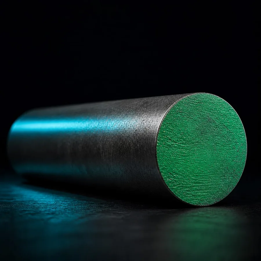
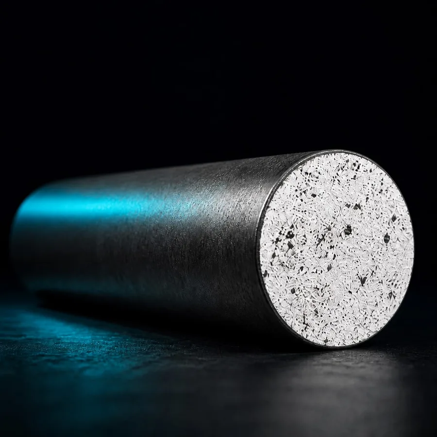
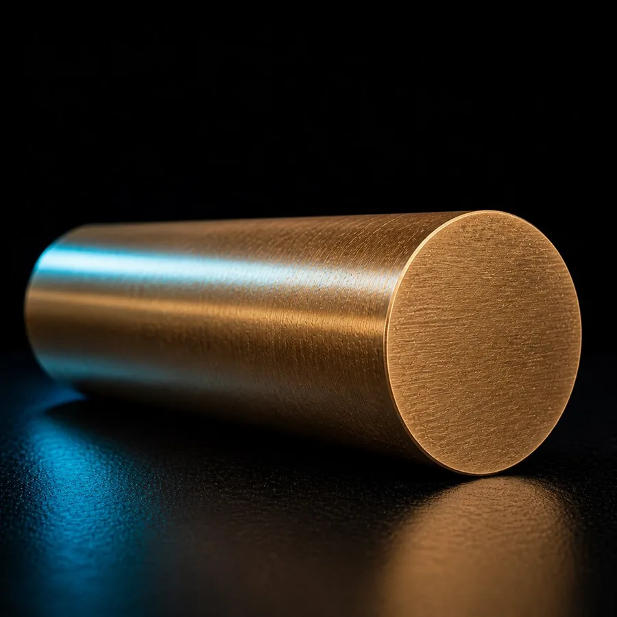
TECTUL supplies the bars these inserts machine every day in Colombian workshops: 1045 steel bar (ISO group P, shafts and machine parts), 4140 steel bar (group P, quenched-and-tempered high-duty components) and SAE 660 bronze bar (group N, bushings and bearings). If your workshop also needs inserts, toolholders or other machining tools, TECTUL quotes them on request: write to us on WhatsApp with the full ISO designation (for example CNMG 120408 plus the material group to be machined) and we will reply with availability and lead time.