 TECTULby IMR
Forged ASTM A105 carbon steel flanges, Classes 150, 300 and 600 (ASME B16.5) — the class is not the pressure
TECTUL · Dispatch across Colombia · Exports to Central & South America
Forged ASTM A105/A105M-24 carbon steel flanges with ASME B16.5 dimensions, drilling and classes, covering the Classes 150, 300 and 600 in the TECTUL catalog and the five types we sell: slip-on, welding neck, blind, threaded and socket weld. The backbone of this sheet is the correction no Colombian supplier publishes: a flange class is not its working pressure. A Class 150 A105 flange is rated 19.6 bar (285 psi) between −29 °C and 38 °C, and above roughly 290 °C it is rated below the 150 psi its name suggests. The sheet publishes the full material group 1.1 pressure-temperature table in bar and psi, the three dimensional tables with drilling and stud length in millimetres and inches, and explains why the socket weld and welding neck references state the pipe schedule (SCH 40, SCH 80).
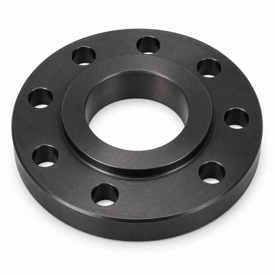
IMPORTANT: reference data — may differ from the physical product; verify with an advisor before buying.
SKU VT-86931 (carbon steel flange, Class 150, slip-on) · 11 carbon steel references in Classes 150, 300 and 600 · slip-on, welding neck, blind, threaded and socket weld types · NPS 1/2″–12″ by reference · sold by the unit
1. Technical specifications
Class 150 dimensions and drilling — ASME B16.5
| NPS | Outside dia. O mm / in | Min. thickness tf mm / in | Hub dia. X mm / in | Length Y threaded, slip-on and socket weld mm / in | Length Y welding neck mm / in | Bore B slip-on and socket weld mm / in | Bolt circle dia. W mm / in | Holes (qty × dia.) | Stud dia. | Stud length, raised face mm / in |
|---|---|---|---|---|---|---|---|---|---|---|
| 1/2 | 90 / 3.50 | 9.6 / 0.38 | 30 / 1.19 | 14 / 0.56 | 46 / 1.81 | 22.2 / 0.88 | 60.3 / 2.38 | 4 × 5/8″ | 1/2″ | 55 / 2.25 |
| 3/4 | 100 / 3.88 | 11.2 / 0.44 | 38 / 1.50 | 14 / 0.56 | 51 / 2.00 | 27.7 / 1.09 | 69.9 / 2.75 | 4 × 5/8″ | 1/2″ | 65 / 2.50 |
| 1 | 110 / 4.25 | 12.7 / 0.50 | 49 / 1.94 | 16 / 0.62 | 54 / 2.12 | 34.5 / 1.36 | 79.4 / 3.12 | 4 × 5/8″ | 1/2″ | 65 / 2.50 |
| 1-1/4 | 115 / 4.62 | 14.3 / 0.56 | 59 / 2.31 | 19 / 0.75 | 56 / 2.19 | 43.2 / 1.70 | 88.9 / 3.50 | 4 × 5/8″ | 1/2″ | 70 / 2.75 |
| 1-1/2 | 125 / 5.00 | 15.9 / 0.62 | 65 / 2.56 | 21 / 0.81 | 60 / 2.38 | 49.5 / 1.95 | 98.4 / 3.88 | 4 × 5/8″ | 1/2″ | 70 / 2.75 |
| 2 | 150 / 6.00 | 17.5 / 0.69 | 78 / 3.06 | 24 / 0.94 | 62 / 2.44 | 61.9 / 2.44 | 120.7 / 4.75 | 4 × 3/4″ | 5/8″ | 85 / 3.25 |
| 2-1/2 | 180 / 7.00 | 20.7 / 0.81 | 90 / 3.56 | 27 / 1.06 | 68 / 2.69 | 74.6 / 2.94 | 139.7 / 5.50 | 4 × 3/4″ | 5/8″ | 90 / 3.50 |
| 3 | 190 / 7.50 | 22.3 / 0.88 | 108 / 4.25 | 29 / 1.12 | 68 / 2.69 | 90.7 / 3.57 | 152.4 / 6.00 | 4 × 3/4″ | 5/8″ | 90 / 3.50 |
| 4 | 230 / 9.00 | 22.3 / 0.88 | 135 / 5.31 | 32 / 1.25 | 75 / 2.94 | 116.1 / 4.57 | 190.5 / 7.50 | 8 × 3/4″ | 5/8″ | 90 / 3.50 |
| 5 | 255 / 10.00 | 22.3 / 0.88 | 164 / 6.44 | 35 / 1.38 | 87 / 3.44 | 143.8 / 5.66 | 215.9 / 8.50 | 8 × 7/8″ | 3/4″ | 95 / 3.75 |
| 6 | 280 / 11.00 | 23.9 / 0.94 | 192 / 7.56 | 38 / 1.50 | 87 / 3.44 | 170.7 / 6.72 | 241.3 / 9.50 | 8 × 7/8″ | 3/4″ | 100 / 4.00 |
| 8 | 345 / 13.50 | 27.0 / 1.06 | 246 / 9.69 | 43 / 1.69 | 100 / 3.94 | 221.5 / 8.72 | 298.5 / 11.75 | 8 × 7/8″ | 3/4″ | 110 / 4.25 |
| 10 | 405 / 16.00 | 28.6 / 1.12 | 305 / 12.00 | 48 / 1.88 | 100 / 3.94 | 276.2 / 10.88 | 362.0 / 14.25 | 12 × 1″ | 7/8″ | 115 / 4.50 |
| 12 | 485 / 19.00 | 30.2 / 1.19 | 365 / 14.38 | 54 / 2.12 | 113 / 4.44 | 327.0 / 12.88 | 431.8 / 17.00 | 12 × 1″ | 7/8″ | 120 / 4.75 |
IMPORTANT
This technical data sheet is a reference guide to the properties of this product type; it is not a quality certificate for the product you are buying. The measurements, dimensions and physical or geometric characteristics of the product supplied may vary by manufacturer, heat and lot, and may even fall outside the cited standards. If any of these figures is critical to your design or build, verify it with one of our advisors against the physical product or the lot's mill certificate, so you can be fully certain of what you are buying. · Original data sheet: tectul.com/en/conduccion-de-fluidos/bridas-y-esparragos/ficha-tecnica-brida-acero-al-carbon-150lb-tipo-slip-on.html
The millimetre values are those of Table 7 and Table 8 of ASME B16.5; the inch values are those of Tables II-7 and II-8 of Mandatory Appendix II of the same standard. They are not our conversions: the standard publishes both series. Bolt and bolt-hole diameters are always expressed in inches, even in the metric tables, by the standard’s own provision. Stud length corresponds to a 2 mm (0.06 in) raised face and does not include the height of the points.
Class 300 dimensions and drilling — ASME B16.5
| NPS | Outside dia. O mm / in | Min. thickness tf mm / in | Hub dia. X mm / in | Length Y threaded, slip-on and socket weld mm / in | Length Y welding neck mm / in | Bore B slip-on and socket weld mm / in | Bolt circle dia. W mm / in | Holes (qty × dia.) | Stud dia. | Stud length, raised face mm / in |
|---|---|---|---|---|---|---|---|---|---|---|
| 1/2 | 95 / 3.75 | 12.7 / 0.50 | 38 / 1.50 | 21 / 0.81 | 51 / 2.00 | 22.2 / 0.88 | 66.7 / 2.62 | 4 × 5/8″ | 1/2″ | 65 / 2.50 |
| 3/4 | 115 / 4.62 | 14.3 / 0.56 | 48 / 1.88 | 24 / 0.94 | 56 / 2.19 | 27.7 / 1.09 | 82.6 / 3.25 | 4 × 3/4″ | 5/8″ | 75 / 3.00 |
| 1 | 125 / 4.88 | 15.9 / 0.62 | 54 / 2.12 | 25 / 1.00 | 60 / 2.38 | 34.5 / 1.36 | 88.9 / 3.50 | 4 × 3/4″ | 5/8″ | 75 / 3.00 |
| 1-1/4 | 135 / 5.25 | 17.5 / 0.69 | 64 / 2.50 | 25 / 1.00 | 64 / 2.50 | 43.2 / 1.70 | 98.4 / 3.88 | 4 × 3/4″ | 5/8″ | 85 / 3.25 |
| 1-1/2 | 155 / 6.12 | 19.1 / 0.75 | 70 / 2.75 | 29 / 1.13 | 67 / 2.63 | 49.5 / 1.95 | 114.3 / 4.50 | 4 × 7/8″ | 3/4″ | 90 / 3.50 |
| 2 | 165 / 6.50 | 20.7 / 0.81 | 84 / 3.31 | 32 / 1.25 | 68 / 2.69 | 61.9 / 2.44 | 127.0 / 5.00 | 8 × 3/4″ | 5/8″ | 90 / 3.50 |
| 2-1/2 | 190 / 7.50 | 23.9 / 0.94 | 100 / 3.94 | 37 / 1.44 | 75 / 2.94 | 74.6 / 2.94 | 149.2 / 5.88 | 8 × 7/8″ | 3/4″ | 100 / 4.00 |
| 3 | 210 / 8.25 | 27.0 / 1.06 | 117 / 4.62 | 41 / 1.63 | 78 / 3.06 | 90.7 / 3.57 | 168.3 / 6.62 | 8 × 7/8″ | 3/4″ | 110 / 4.25 |
| 4 | 255 / 10.00 | 30.2 / 1.19 | 146 / 5.75 | 46 / 1.82 | 84 / 3.32 | 116.1 / 4.57 | 200.0 / 7.88 | 8 × 7/8″ | 3/4″ | 115 / 4.50 |
| 5 | 280 / 11.00 | 33.4 / 1.31 | 178 / 7.00 | 49 / 1.94 | 97 / 3.82 | 143.8 / 5.66 | 235.0 / 9.25 | 8 × 7/8″ | 3/4″ | 120 / 4.75 |
| 6 | 320 / 12.50 | 35.0 / 1.38 | 206 / 8.12 | 51 / 2.00 | 97 / 3.82 | 170.7 / 6.72 | 269.9 / 10.62 | 12 × 7/8″ | 3/4″ | 120 / 4.75 |
| 8 | 380 / 15.00 | 39.7 / 1.56 | 260 / 10.25 | 60 / 2.38 | 110 / 4.32 | 221.5 / 8.72 | 330.2 / 13.00 | 12 × 1″ | 7/8″ | 140 / 5.50 |
| 10 | 445 / 17.50 | 46.1 / 1.81 | 321 / 12.62 | 65 / 2.56 | 116 / 4.56 | 276.2 / 10.88 | 387.4 / 15.25 | 16 × 1-1/8″ | 1″ | 160 / 6.25 |
| 12 | 520 / 20.50 | 49.3 / 1.94 | 375 / 14.75 | 71 / 2.82 | 129 / 5.06 | 327.0 / 12.88 | 450.8 / 17.75 | 16 × 1-1/4″ | 1-1/8″ | 170 / 6.75 |
IMPORTANT: reference data — may differ from the physical product; verify with an advisor before buying.
Class 600 dimensions and drilling — ASME B16.5
| NPS | Outside dia. O mm / in | Min. thickness tf mm / in | Hub dia. X mm / in | Length Y threaded, slip-on and socket weld mm / in | Length Y welding neck mm / in | Bore B slip-on and socket weld mm / in | Bolt circle dia. W mm / in | Holes (qty × dia.) | Stud dia. | Stud length, raised face mm / in |
|---|---|---|---|---|---|---|---|---|---|---|
| 1/2 | 95 / 3.75 | 14.3 / 0.56 | 38 / 1.50 | 22 / 0.88 | 52 / 2.06 | 22.2 / 0.88 | 66.7 / 2.62 | 4 × 5/8″ | 1/2″ | 75 / 3.00 |
| 3/4 | 115 / 4.62 | 15.9 / 0.62 | 48 / 1.88 | 25 / 1.00 | 57 / 2.25 | 27.7 / 1.09 | 82.6 / 3.25 | 4 × 3/4″ | 5/8″ | 90 / 3.50 |
| 1 | 125 / 4.88 | 17.5 / 0.69 | 54 / 2.12 | 27 / 1.06 | 62 / 2.44 | 34.5 / 1.36 | 88.9 / 3.50 | 4 × 3/4″ | 5/8″ | 90 / 3.50 |
| 1-1/4 | 135 / 5.25 | 20.7 / 0.81 | 64 / 2.50 | 29 / 1.12 | 67 / 2.62 | 43.2 / 1.70 | 98.4 / 3.88 | 4 × 3/4″ | 5/8″ | 95 / 3.75 |
| 1-1/2 | 155 / 6.12 | 22.3 / 0.88 | 70 / 2.75 | 32 / 1.25 | 70 / 2.75 | 49.5 / 1.95 | 114.3 / 4.50 | 4 × 7/8″ | 3/4″ | 110 / 4.25 |
| 2 | 165 / 6.50 | 25.4 / 1.00 | 84 / 3.31 | 37 / 1.44 | 73 / 2.88 | 61.9 / 2.44 | 127.0 / 5.00 | 8 × 3/4″ | 5/8″ | 110 / 4.25 |
| 2-1/2 | 190 / 7.50 | 28.6 / 1.12 | 100 / 3.94 | 41 / 1.62 | 79 / 3.12 | 74.6 / 2.94 | 149.2 / 5.88 | 8 × 7/8″ | 3/4″ | 120 / 4.75 |
| 3 | 210 / 8.25 | 31.8 / 1.25 | 117 / 4.62 | 46 / 1.81 | 83 / 3.25 | 90.7 / 3.57 | 168.3 / 6.62 | 8 × 7/8″ | 3/4″ | 125 / 5.00 |
| 4 | 275 / 10.75 | 38.1 / 1.50 | 152 / 6.00 | 54 / 2.12 | 102 / 4.00 | 116.1 / 4.57 | 215.9 / 8.50 | 8 × 1″ | 7/8″ | 145 / 5.75 |
| 5 | 330 / 13.00 | 44.5 / 1.75 | 189 / 7.44 | 60 / 2.38 | 114 / 4.50 | 143.8 / 5.66 | 266.7 / 10.50 | 8 × 1-1/8″ | 1″ | 165 / 6.50 |
| 6 | 355 / 14.00 | 47.7 / 1.88 | 222 / 8.75 | 67 / 2.62 | 117 / 4.62 | 170.7 / 6.72 | 292.1 / 11.50 | 12 × 1-1/8″ | 1″ | 170 / 6.75 |
| 8 | 420 / 16.50 | 55.6 / 2.19 | 273 / 10.75 | 76 / 3.00 | 133 / 5.25 | 221.5 / 8.72 | 349.2 / 13.75 | 12 × 1-1/4″ | 1-1/8″ | 190 / 7.50 |
| 10 | 510 / 20.00 | 63.5 / 2.50 | 343 / 13.50 | 86 / 3.38 | 152 / 6.00 | 276.2 / 10.88 | 431.8 / 17.00 | 16 × 1-3/8″ | 1-1/4″ | 215 / 8.50 |
| 12 | 560 / 22.00 | 66.7 / 2.62 | 400 / 15.75 | 92 / 3.62 | 156 / 6.12 | 327.0 / 12.88 | 489.0 / 19.25 | 20 × 1-3/8″ | 1-1/4″ | 220 / 8.75 |
IMPORTANT: reference data — may differ from the physical product; verify with an advisor before buying.
In Class 600 the raised face is 7 mm (0.25 in) rather than 2 mm, and the tabulated stud length corresponds to that face. The bore B of Class 600 welding neck and socket weld flanges is specified by the purchaser: the standard does not tabulate it (Table 16, note 4). The value published here in the “bore B slip-on and socket weld” column for Class 600 is the slip-on bore, which is tabulated.
The tf thickness includes the raised face
This is the most frequent dimensional confusion when measuring a flange at goods receipt. The minimum thickness tf of Tables 8, 11 and 16 corresponds to the flange with its standard raised face —2 mm (0.06 in) in Classes 150 and 300, 7 mm (0.25 in) from Class 400 up—. The note to those tables states it explicitly: when the flange is supplied flat faced, its thickness is either the full tf plus 2 mm, or the tf without the raised face height. That is: a flat-faced Class 150 NPS 4 flange may measure 22.3 mm (the tabulated tf, if the raised face was removed) or 24.3 mm (if the raised face was added to the thickness), and both comply with the standard.
Material: forged carbon steel ASTM A105/A105M-24
| Element | Limit (mass %) | Element | Limit (mass %) |
|---|---|---|---|
| Carbon (C) | ≤ 0.35 | Copper (Cu) | ≤ 0.40 |
| Manganese (Mn) | 0.60 – 1.05 | Nickel (Ni) | ≤ 0.40 |
| Phosphorus (P) | ≤ 0.035 | Chromium (Cr) | ≤ 0.30 |
| Sulfur (S) | ≤ 0.040 | Molybdenum (Mo) | ≤ 0.12 |
| Silicon (Si) | 0.10 – 0.35 | Vanadium (V) | ≤ 0.08 |
| Sum Cu + Ni + Cr + Mo + V | ≤ 1.00 | Sum Cr + Mo | ≤ 0.32 |
| Mechanical property | Minimum requirement of ASTM A105/A105M-24 |
|---|---|
| Tensile strength Rₘ | 485 MPa (70,000 psi / 70 ksi) |
| Yield strength Rₑ | 250 MPa (36,000 psi / 36 ksi) |
| Elongation in 50 mm (2″) | 30 % |
| Reduction of area | 30 % |
| Hardness | 137 – 197 HBW (a range, not just a maximum) |
The upper hardness limit moved from 187 HB to 197 HBW in the 2021 edition of A105 and is retained in the 2024 edition: a certificate reading 195 HBW complies with the current standard and would not have complied with a pre-2021 edition. Whatever figure appears on the material certificate must be read against the edition that certificate declares.
General specifications
| Product | Forged carbon steel flanges for bolted pipe joints, in five types: slip-on, welding neck, blind, NPT threaded and socket weld |
| Material | Forged carbon steel ASTM A105/A105M-24 — ASME B16.5 material group 1.1 (the same group as cast A216 grade WCB) |
| Dimensional and class standard | ASME B16.5 — Pipe Flanges and Flanged Fittings: NPS 1/2 Through NPS 24, Metric/Inch Standard |
| Catalog classes | 150, 300 and 600 (the standard also tabulates 400, 900, 1500 and 2500) |
| Face | Raised face of 2 mm / 0.06 in in Classes 150 and 300, and 7 mm / 0.25 in in Class 600; serrated concentric or spiral finish with average roughness Rₐ from 3.2 to 6.3 µm (125 to 250 µin) per ASME B16.5, para. 6.4.5.3 |
| Commercial range | NPS 1/2″–12″ by reference and class; the blind flange references reach NPS 24″ in the catalog. Diameters above 12″ are quoted on request |
| Marking required by the standard | Manufacturer name or trademark · ASTM specification and grade (A105) · class designation (150, 300 or 600) · designation “B16” or “B16.5” · NPS · on cast parts also the melt number (ASME B16.5, section 4, on the basis of MSS SP-25) |
| Sale | By the unit, per reference, type, class and diameter |
| Applicable standards | ASME B16.5 (dimensions, classes, pressure-temperature table and marking) · ASTM A105/A105M-24 (forged material) · ASME B1.20.1 (NPT thread of threaded flanges) · ASME B36.10M (pipe inside diameter that sets the bore) · ASME B16.20 and ASME B16.21 (gaskets) · ASME B1.1 (bolting thread) · ASME PCC-1 (assembly and tightening) |
IMPORTANT: reference data — may differ from the physical product; verify with an advisor before buying.
2. Engineering basis: the class is not the pressure
The rule in one line
A Class 150 carbon steel flange does not withstand 150 psi: it withstands 285 psi (19.6 bar) between −29 °C and 38 °C. A flange class is a series designation —the name of a column in the ASME B16.5 pressure-temperature table—, not the working pressure. The allowable pressure comes from the intersection of class, material group and service temperature. For forged A105 carbon steel the group is 1.1, and this is its table.
Pressure-temperature table for material group 1.1 (A105) — in bar
| Temperature, °C | Class 150, bar | Class 300, bar | Class 600, bar |
|---|---|---|---|
| −29 to 38 | 19.6 | 51.1 | 102.1 |
| 50 | 19.2 | 50.1 | 100.2 |
| 100 | 17.7 | 46.6 | 93.2 |
| 150 | 15.8 | 45.1 | 90.2 |
| 200 | 13.8 | 43.8 | 87.6 |
| 250 | 12.1 | 41.9 | 83.9 |
| 300 | 10.2 | 39.8 | 79.6 |
| 325 | 9.3 | 38.7 | 77.4 |
| 350 | 8.4 | 37.6 | 75.1 |
| 375 | 7.4 | 36.4 | 72.7 |
| 400 | 6.5 | 34.7 | 69.4 |
| 425 | 5.5 | 28.8 | 57.5 |
| 450 | 4.6 | 23.0 | 46.0 |
| 475 | 3.7 | 17.4 | 34.9 |
| 500 | 2.8 | 11.8 | 23.5 |
| 538 | 1.4 | 5.9 | 11.8 |
IMPORTANT: reference data — may differ from the physical product; verify with an advisor before buying.
The same table in imperial units — in psi
| Temperature, °F | Class 150, psi | Class 300, psi | Class 600, psi |
|---|---|---|---|
| −20 to 100 | 285 | 740 | 1,480 |
| 200 | 260 | 680 | 1,360 |
| 300 | 230 | 655 | 1,310 |
| 400 | 200 | 635 | 1,265 |
| 500 | 170 | 605 | 1,205 |
| 600 | 140 | 570 | 1,135 |
| 650 | 125 | 550 | 1,100 |
| 700 | 110 | 530 | 1,060 |
| 750 | 95 | 505 | 1,015 |
| 800 | 80 | 410 | 825 |
| 850 | 65 | 320 | 640 |
| 900 | 50 | 230 | 460 |
| 950 | 35 | 135 | 275 |
| 1,000 | 20 | 85 | 170 |
IMPORTANT: reference data — may differ from the physical product; verify with an advisor before buying.
Both tables are those of ASME B16.5 (Table 2-1.1 in bar and Table II-2-1.1 of Mandatory Appendix II in psi) for material group 1.1, which groups the A105 and A350 grade LF2 and LF3 forgings, the A216 grade WCB casting and the A515 and A516 grade 70 plates. The temperature steps of the metric and imperial tables do not correspond to each other (38 °C is not exactly 100 °F, 538 °C is not exactly 1,000 °F): each table is read in its own units and values are not interpolated between them. Above 425 °C the carbide phase of the steel may convert to graphite: the standard permits it but does not recommend it for prolonged service.
How to read the table: a four-step method
- Take the design temperature of the service, not the ambient temperature nor the normal running fluid temperature: the design one, which is what the line code governs.
- Move up to the next tabulated step. If your design temperature is 215 °C, read the 250 °C row, never the 200 °C one. Interpolating downwards is what produces joints that weep on a hot start-up.
- Compare the allowable pressure of that row with the design pressure. If the design pressure exceeds it, the class does not serve: you must move up a class, not tighten harder.
- Check the gasket and the bolting, which are almost always the weakest link: the gasket material may have a thermal ceiling far below what the table allows the steel.
- Data: design pressure 8 bar (116 psi), design temperature 180 °C, A105 carbon steel flanges (material group 1.1).
- Temperature step to use: 180 °C is not tabulated; move up to the next step, which is 200 °C.
- Reading Class 150 at 200 °C: 13.8 bar. Since 13.8 bar is greater than 8 bar, Class 150 complies with a margin of 1.7 times the design pressure.
- Contrast with the wrong intuition: whoever reads “Class 150 = 150 psi = 10.3 bar” and subtracts a mental derating would arrive at a very different figure and would very likely reject a flange that does comply. The table is the only thing that decides.
- The real limit on this line is not the flange: at 200 °C the Class 150 steel is rated 13.8 bar, but the joint gasket —and very particularly any elastomer- or PTFE-bearing gasket— may fall out of range. Gasket selection is made separately and against ASME B16.20 or ASME B16.21, and the final tightening torque is set by the gasket, not by the flange.
- Question: the “150” designation suggests 150 psi. At what temperature is a Class 150 flange actually rated 150 psi?
- Reading the psi table: at 500 °F it is rated 170 psi and at 600 °F it is rated 140 psi. The 150 psi falls between those two steps.
- Consequence: at around 550 °F (roughly 290 °C) the Class 150 carbon steel flange stops being rated for the 150 psi of its name. Below that temperature it is rated above its designation —up to 285 psi cold— and above it, below.
- A citable rule: the class designation coincides with the group 1.1 allowable pressure at a single temperature, around 290 °C. Across the rest of the range, coinciding is the exception.
What the class does determine, besides the pressure
Moving from Class 150 to Class 300 at the same NPS does not only change the allowable pressure: it changes the bolt circle, the quantity and diameter of the studs, the outside diameter and the thickness. At NPS 2″, Class 150 carries 4 studs of 5/8″ on a 120.7 mm circle and Class 300 carries 8 studs of 5/8″ on a 127.0 mm circle. They are geometrically incompatible flanges: a Class 150 flange cannot be bolted against a Class 300 even at the same nominal diameter, because the holes do not line up. They do not line up at NPS 1/2″ either, the only diameter in the catalog where all three classes share bolt quantity and diameter: the bolt circle is 60.3 mm in Class 150 and 66.7 mm in Classes 300 and 600.
3. Why the catalog states the schedule: bore, types and welding
A flange bore is not set by the flange: it is set by the pipe
Four catalog references carry the pipe schedule in their name —“Class 150 SCH 40 socket weld”, “Class 300 SCH 40 socket weld”, “Class 300 SCH 80 welding neck”— and that is not a commercial label: it is the datum without which the part cannot be made. On a slip-on, blind or threaded flange, the inner hole is tabulated in ASME B16.5 and depends only on NPS. On a welding neck or socket weld flange, the inner hole must reproduce the inside diameter of the pipe it will be welded to, and that inside diameter changes with the schedule.
The standard resolves it this way: the bore that Table 8 tabulates for Class 150 and 300 welding neck and socket weld flanges corresponds to the inside diameter of standard wall pipe per ASME B36.10M —which at NPS 10″ and smaller is the same as Schedule 40—, and that is the bore supplied unless the purchaser specifies otherwise. In Class 600 the standard does not tabulate the bore of welding neck and socket weld flanges: Table 16 refers it explicitly to the purchaser.
| Flange type | What does the inner hole depend on? | Datum required when ordering |
|---|---|---|
| Slip-on | Only on NPS: ASME B16.5 tabulates it in column B (slip-on and socket welding) | NPS and class |
| Blind | It has no through hole | NPS and class |
| Threaded | On the NPT thread per ASME B1.20.1, which depends only on NPS | NPS and class |
| Welding neck | On the pipe inside diameter, which changes with the schedule | NPS, class and pipe schedule |
| Socket weld | On the pipe outside diameter for the socket and the inside diameter for the bore | NPS, class and pipe schedule |
Practical consequence: the flange and the pipe are ordered together
Ordering “NPS 3 Class 300 welding neck flange” without stating the schedule leaves the specification incomplete: the flange will arrive with the standard wall bore and, if the line is SCH 80, an internal step will remain at the weld root. That step concentrates stress, retains solids and is a fatigue crack initiation point. That is why our welding neck and socket weld references name the schedule: it is not redundancy, it is the only way for the part to match the pipe. The pipe dimensional data by schedule live in the carbon steel pipe family data sheets, not here.
The double weld of the slip-on flange
The slip-on flange slides over the pipe and is welded with two fillet welds: an outer one at the back face of the hub and an inner one at the pipe end, against the flange face. The inner weld is not optional on a joint that will contain pressure: without it, fluid enters the clearance between pipe and flange and the joint fails by crevice corrosion and by fatigue of the single outer weld. This is the assembly detail most often skipped in the field and it has no relation to the class: a badly welded Class 600 slip-on fails just like a Class 150 one.
The welding neck flange, by contrast, is joined with a single butt weld with bevel preparation, and that weld is radiographable end to end. That is the real difference between the two types: not the pressure they are rated for —at the same class and material the pressure-temperature table is identical— but the quality and inspectability of the welded joint, and the behaviour under fatigue and thermal cycling, where the tapered neck spreads the stress that the slip-on concentrates in the weld.
The five catalog types, compared
| Type | Joint to the pipe | Inspected by | Where it is specified |
|---|---|---|---|
| Slip-on | Two fillet welds (outer and inner) | Visual inspection; the inner weld is not radiographable | Static service, fast assembly, water and air lines |
| Welding neck | A single butt weld with bevel | Radiography or ultrasonic testing end to end | Cyclic service, fatigue, high temperature, certified welding |
| Socket weld | Pipe socket plus one outer fillet weld | Visual inspection and liquid penetrant testing | Small diameters, high pressure, where a butt joint does not fit |
| Threaded | NPT thread per ASME B1.20.1, no welding | Thread verification and pressure test | Lines where welding is not permitted, frequent assembly and disassembly |
| Blind | Not joined to pipe: it closes the flanged end | Visual inspection and pressure test | Line closure, future inspection point, hydrostatic test |
4. Frequently asked questions
How much pressure does a Class 150 carbon steel flange withstand?
19.6 bar (285 psi) between −29 °C and 38 °C, if it is forged A105 carbon steel or any other ASME B16.5 group 1.1 material. It is not 150 psi: the class is a series designation, not the working pressure. The allowable pressure falls with temperature in a tabulated way: 13.8 bar at 200 °C, 10.2 bar at 300 °C and 1.4 bar at 538 °C. The “150” designation only coincides with the allowable pressure at around 290 °C; below that the flange is rated higher and above it, lower.
Can I bolt a Class 150 flange against a Class 300 of the same diameter?
No. The drilling is different: at NPS 2″ Class 150 has 4 holes of 3/4″ on a 120.7 mm circle and Class 300 has 8 holes of 3/4″ on a 127.0 mm circle. Neither the quantity nor the position match, so there is no way to pass the studs. They do not match at NPS 1/2″ either, where both classes carry 4 studs of 1/2″ but on circles of 60.3 mm and 66.7 mm respectively. When two systems of different class must be joined, a spool with one flange of each class is used, or a transition flange made for the case.
What is the real difference between a slip-on and a welding neck flange?
At the same class and the same material, the allowable pressure is identical: ASME B16.5 tabulates them in the same column of the same pressure-temperature table. The difference lies in the welded joint. The slip-on slides over the pipe and needs two fillet welds, outer and inner; the welding neck is joined with a single butt weld, bevelled and radiographable end to end, and its tapered neck spreads the stress instead of concentrating it in the weld. That is why the welding neck is the one specified for cyclic service, fatigue, high temperature and wherever the weld must be certified by non-destructive examination; the slip-on is cheaper, faster to align and sufficient in static service.
Why does the socket weld reference say SCH 40 and the welding neck one say SCH 80?
Because in those two constructions the inner hole of the flange must reproduce the pipe inside diameter, and that diameter changes with the schedule. ASME B16.5 tabulates the bore of Class 150 and 300 welding neck and socket weld flanges for standard wall pipe per ASME B36.10M —which at NPS 10″ and smaller is Schedule 40— and supplies it that way unless the purchaser asks for another. In Class 600 the standard does not tabulate it: the purchaser specifies it. Ordering a welding neck flange without declaring the schedule leaves an internal step at the weld root if the pipe is not standard wall.
How many studs, and what size, does an NPS 4 flange take?
It depends on the class. Class 150: 8 studs of 5/8″, length 90 mm (3.50 in), on a 190.5 mm (7.50 in) circle. Class 300: 8 studs of 3/4″, length 115 mm (4.50 in), on a 200.0 mm (7.88 in) circle. Class 600: 8 studs of 7/8″, length 145 mm (5.75 in), on a 215.9 mm (8.50 in) circle. The lengths are those of the standard raised face and do not include the height of the stud points. Material, tightening torque and sequence live in the flange stud and bolting data sheet.
Does the thickness I measure with a caliper include the raised face?
Yes. The tf thickness that ASME B16.5 tabulates corresponds to the flange with its standard raised face: 2 mm (0.06 in) in Classes 150 and 300, and 7 mm (0.25 in) from Class 400 up. That is why a flat-faced flange may measure the tabulated tf minus the raised face, or tf plus 2 mm, and both versions comply with the standard. If you are comparing a measured thickness against a table, first check which of the two cases you are holding.
Does the same A105 flange serve for potable water and for steam?
The flange does, within its pressure-temperature table; the joint as a whole does not always. In potable water the problem is not pressure but corrosion: carbon steel rusts in permanent contact with water and that rust ends up on the sealing face. In steam the problem is the gasket and the thermal cycling, not the steel. In both cases the material decision is taken against the fluid and not against the class: when the fluid demands corrosion resistance, selection moves to forged A182 stainless steel flanges and to their own pressure-temperature table, which is not the same.
5. Application notes
Feasibility
The forged A105 carbon steel flange is the standard demountable bolted-joint solution on process lines, industrial water, compressed air, steam and fire protection, when the fluid does not demand corrosion resistance in the flange metal. It is not specified for sanitary food service, for chloride-bearing fluids, nor for water in permanent contact where oxidation of the sealing face would be unacceptable: there selection moves to forged A182 stainless flanges and to their own pressure-temperature table. The flange also corrodes externally outdoors or in damp environments, so the external coating is part of the specification. The class is chosen by the pressure-temperature intersection of the material group 1.1 table, never by the name of the class.
Installation
On the slip-on flange weld both fillet welds —outer at the back face of the hub and inner at the pipe end—: the inner one is not optional on a joint that contains pressure. On the welding neck flange respect the bevel preparation and the alignment before welding. Check that the two mating flanges are of the same class and the same nominal diameter before attempting to pass the studs: the bolt circles of different classes do not match at any diameter in the catalog. Align the faces parallel before tightening; correcting a misalignment by tightening distorts the flange and ruins the gasket. Tighten in a cross pattern in passes per ASME PCC-1, never circularly and never in a single go. After any mechanical intervention restore the external coating. In Class 600, confirm the bore of the welding neck or socket weld flange before welding: the standard does not tabulate it and it depends on the pipe schedule.
Design
Do not specify the class by its name. Enter the material group 1.1 pressure-temperature table with the line design temperature, move up to the next tabulated step and compare the allowable pressure of that row with the design pressure. Remember that the class also determines the joint geometry —bolt circle, stud quantity and diameter, outside diameter and thickness— and that this is why two different classes are not bolted to one another. Gasket and bolting are selected separately and are usually the link that sets the real limit of the joint: tightening torque is determined by the gasket under ASME PCC-1 and not by the flange. The figures in this sheet are those of the standard for material complying with A105; they do not replace the calculation of the engineer responsible for the line under the project code (ASME B31.3, ASME B31.1, the applicable NTC or other) and its current edition, with the load cases, corrosion allowance and external loads of the actual service.
6. Technical notice and limitation of liability
The dimensions, drilling and ratings in this sheet are the values tabulated in ASME B16.5 for raised face flanges and the minimum properties of ASTM A105/A105M: they guide specification and are not a certificate of conformance for any lot. The millimetre and inch series are both published by the standard, not conversions of ours. The minimum thickness tf corresponds to the flange with its standard raised face (2 mm in Classes 150 and 300; 7 mm from Class 400 up): a catalog publishing the thickness without the raised face gives 2 mm less on the same part and neither is wrong. Beware the dimensional tables circulating as PDFs: the most cited one in the Colombian market reproduces the 1961 edition of B16.5, and the current one is 2025.
The dimensional scope published here is NPS 1/2″ to 12″ in Classes 150, 300 and 600. The larger sizes some catalog types reach (up to 30″ in the Class 150 welding neck and 24″ in the blinds) follow the same standard but fall outside these tables and are confirmed on quotation; from NPS 26 up the applicable standard is no longer B16.5 but ASME B16.47. The bore of welding neck and socket weld flanges depends on the pipe schedule, and in Class 600 the standard does not tabulate it: the purchaser specifies it. Gasket, studs and nuts are not supplied with the flange and are usually the link that sets the joint's real limit.
Certifying a lot requires the manufacturer's material test certificate per ASTM A105/A105M, with the heat composition and the test results, tied by heat number to the marking on the part. Final selection of class, material, flange type, face and gasket is the responsibility of the line designer per the project code (ASME B31.3, ASME B31.1, the applicable NTC or other) and its current edition. This sheet does not replace the bolted joint calculation or the project's welding procedure.
Sources
- ASME B16.5 — Pipe Flanges and Flanged Fittings: NPS 1/2 Through NPS 24, Metric/Inch Standard. Edición vigente: ASME B16.5-2025, aprobada por ANSI el 10 de abril de 2025; la norma está en mantenimiento estabilizado. Los valores publicados en esta ficha se verificaron sobre el texto de la edición ASME B16.5-2017: Tabla 2-1.1 y Tabla II-2-1.1 (presión-temperatura del grupo de materiales 1.1 en bar y en psi), Tablas 7, 8, II-7 y II-8 (clase 150), Tablas 10, 11, II-10 y II-11 (clase 300), Tablas 15, 16, II-15 y II-16 (clase 600), capítulo 4 (marcado), párrafo 6.4.5.3 (acabado de la cara de sellado), nota 7 de la Tabla 8 (bore según diámetro interior de tubo de pared estándar) y nota 4 de la Tabla 16 (bore a especificar por el comprador en clase 600)
- ASTM A105/A105M-24 — Standard Specification for Carbon Steel Forgings for Piping Applications (composición química, propiedades mecánicas mínimas y rango de dureza 137–197 HBW del acero al carbón forjado de las bridas; el límite superior de dureza pasó de 187 HB a 197 HBW en la edición 2021)
- ASME B36.10M — Welded and Seamless Wrought Steel Pipe (diámetro interior de tubo de pared estándar y por cédula, que fija el bore de las bridas con cuello y socket weld según la nota 7 de la Tabla 8 de ASME B16.5)
- ASME B1.20.1 — Pipe Threads, General Purpose, Inch (rosca NPT de las bridas roscadas)
- ASME B1.1 — Unified Inch Screw Threads, UN and UNR Thread Form (serie de rosca de la tornillería de brida: serie basta hasta 1″ y serie de ocho hilos por pulgada por encima, según la Tabla 1C de ASME B16.5)
- ASME PCC-1 — Guidelines for Pressure Boundary Bolted Flange Joint Assembly (apriete por pasadas en secuencia cruzada y determinación del par objetivo; ecuaciones y tablas verificadas sobre la edición ASME PCC-1-2019)
- ASME B16.20-2023 — Metallic Gaskets for Pipe Flanges: Ring-Joint, Spiral-Wound, and Jacketed, y ASME B16.21-2021 — Nonmetallic Flat Gaskets for Pipe Flanges (normas de empaque de la unión bridada; el empaque se selecciona contra ellas y no contra esta ficha)
- MSS SP-25 — Standard Marking System for Valves, Fittings, Flanges, and Unions (base del marcado que exige el capítulo 4 de ASME B16.5)
- Catálogo TECTUL, familia bridas y espárragos (agosto de 2026): 11 referencias de acero al carbón en clases 150, 300 y 600, tipos slip-on, con cuello, ciega, roscada y socket weld, y sus diámetros publicados por referencia
This data sheet is the property of TECTUL, part of the Industrias IMR group. Reproduction without attribution is prohibited. Original document and updates: tectul.com/en/conduccion-de-fluidos/bridas-y-esparragos/ficha-tecnica-brida-acero-al-carbon-150lb-tipo-slip-on.html.