
Hydraulic hose, double braided steel wire reinforcement — SAE 100R2 / 100R2AT, EN 853 2SN
TECTUL · Dispatch across Colombia · Exports to Central & South America
Hydraulic hose with two braided steel wire layers, the next pressure step above the single-braid R1/R1AT family. The TECTUL catalog covers two references of the same type+material: SAE 100R2 AT (nitrile tube and cover, with its own product page, sold as bulk hose by the 100 m roll) and its standard SAE 100R2 sibling (synthetic rubber tube and cover, alias manguera-hidraulica-r2-x-rollo, whose own manufacturer sheet explicitly cites EN 853-2SN and ISO 1436). Both share a 1:4 safety ratio verified in every row of their tables.
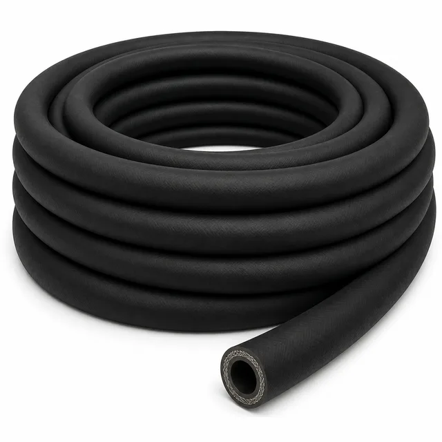
IMPORTANT: reference data — may differ from the physical product; verify with an advisor before buying.
SKU VT-142232 (SAE 100 R2 AT hose) · 2 references of the same type+material · 12 diameters from 3/16″ to 2″ (AT) and 9 from 1/4″ to 2″ (standard) · sold by the roll
1. Technical specifications
Dimensional and pressure table — SAE 100R2 AT (main reference, manguera-sae-100-r2-at)
| Nominal | ID (mm) | OD (mm) | Working pressure W/P | Burst pressure B/P | Min. bend radius | Aprox. weight |
|---|---|---|---|---|---|---|
| 3/16″ (4.8 mm) | 4.8 | 14.1 | 5000 psi / 344.7 bar | 20000 psi / 1379.0 bar | 90 mm (3.5″) | 0.31 kg/m |
| 1/4″ (6.4 mm) | 6.4 | 15.2 | 5000 psi / 344.7 bar | 20000 psi / 1379.0 bar | 100 mm (3.9″) | 0.36 kg/m |
| 5/16″ (7.9 mm) | 7.9 | 16.8 | 4250 psi / 293.0 bar | 17000 psi / 1172.1 bar | 115 mm (4.5″) | 0.41 kg/m |
| 3/8″ (9.5 mm) | 9.5 | 19.2 | 4000 psi / 275.8 bar | 16000 psi / 1103.2 bar | 130 mm (5.1″) | 0.54 kg/m |
| 1/2″ (12.7 mm) | 12.7 | 22.2 | 3500 psi / 241.3 bar | 14000 psi / 965.3 bar | 180 mm (7.1″) | 0.64 kg/m |
| 5/8″ (15.9 mm) | 15.9 | 25.2 | 2750 psi / 189.6 bar | 11000 psi / 758.4 bar | 200 mm (7.9″) | 0.73 kg/m |
| 3/4″ (19.0 mm) | 19.0 | 29.5 | 2250 psi / 155.1 bar | 9000 psi / 620.5 bar | 240 mm (9.4″) | 0.92 kg/m |
| 7/8″ (22.2 mm) | 22.2 | 32.8 | 2000 psi / 137.9 bar | 8000 psi / 551.6 bar | 280 mm (11.0″) | 1.15 kg/m |
| 1″ (25.4 mm) | 25.4 | 38.0 | 2000 psi / 137.9 bar | 8000 psi / 551.6 bar | 300 mm (11.8″) | 1.25 kg/m |
| 1-1/4″ (31.8 mm) | 31.8 | 48.6 | 1625 psi / 112.0 bar | 6500 psi / 448.2 bar | 420 mm (16.5″) | 2.15 kg/m |
| 1-1/2″ (38.1 mm) | 38.1 | 55.0 | 1250 psi / 86.2 bar | 5000 psi / 344.7 bar | 500 mm (19.7″) | 2.65 kg/m |
| 2″ (50.8 mm) | 50.8 | 67.6 | 1125 psi / 77.5 bar | 4500 psi / 310.3 bar | 635 mm (25.0″) | 3.36 kg/m |
IMPORTANT
This technical data sheet is a reference guide to the properties of this product type; it is not a quality certificate for the product you are buying. The measurements, dimensions and physical or geometric characteristics of the product supplied may vary by manufacturer, heat and lot, and may even fall outside the cited standards. If any of these figures is critical to your design or build, verify it with one of our advisors against the physical product or the lot's mill certificate, so you can be fully certain of what you are buying. · Original data sheet: tectul.com/en/conduccion-de-fluidos/mangueras/ficha-tecnica-manguera-sae-100-r2-at.html
Minimum bend radius: from 90 mm (3.5″) at 3/16″ to 635 mm (25.0″) at 2″. Weight: from 0.31 kg/m (0.21 lb/ft) at 3/16″ to 3.36 kg/m (2.26 lb/ft) at 2″. Bar values are calculated from the manufacturer sheet's psi figure using the exact conversion 1 psi = 0.0689476 bar; this table does not show the row inconsistencies found in the standard reference's sheet (see below).
Dimensional and pressure table — standard SAE 100R2 (sibling reference, alias manguera-hidraulica-r2-x-rollo)
| Nominal | ID (mm) | OD (mm) | Working pressure W/P | Burst pressure B/P | Min. bend radius | Aprox. weight |
|---|---|---|---|---|---|---|
| 1/4″ (6.7 mm) | 6.7 | 14.7 | 5800 psi / 399.9 bar | 23200 psi / 1599.6 bar | 100 mm (3.9″) | 0.386 kg/m |
| 3/8″ (9.7 mm) | 9.7 | 17.2 | 4785 psi / 329.9 bar | 19140 psi / 1319.7 bar | 64 mm (2.5″) | 0.66 kg/m |
| 1/2″ (12.9 mm) | 12.9 | 20.9 | 3900 psi / 268.9 bar | 15950 psi / 1099.8 bar | 89 mm (3.5″) | 0.852 kg/m |
| 5/8″ (16.1 mm) | 16.1 | 24.5 | 3625 psi / 249.9 bar | 14500 psi / 999.7 bar | 102 mm (4.0″) | 1.059 kg/m |
| 3/4″ (19.2 mm) | 19.2 | 28.0 | 3120 psi / 215.1 bar | 12470 psi / 859.7 bar | 121 mm (4.8″) | 1.134 kg/m |
| 1″ (25.7 mm) | 25.7 | 34.9 | 2395 psi / 165.1 bar | burst not verifiable (see note) | 153 mm (6.0″) | 1.980 kg/m |
| 1-1/4″ (32.4 mm) | 32.4 | 43.9 | 1815 psi / 125.1 bar | 7250 psi / 499.9 bar | 210 mm (8.3″) | 2.822 kg/m |
| 1-1/2″ (38.5 mm) | 38.5 | 50.4 | 1305 psi / 90.0 bar | 5220 psi / 359.9 bar | 254 mm (10.0″) | 3.229 kg/m |
| 2″ (51.4 mm) | 51.4 | 63.6 | 1160 psi / 80.0 bar | 4640 psi / 319.9 bar | 318 mm (12.5″) | 4.622 kg/m |
IMPORTANT: reference data — may differ from the physical product; verify with an advisor before buying.
This standard reference's manufacturer sheet prints "950/660" in the burst-pressure column of the 1″ row: that pair does not fit the table's progression (it should be near 9500 psi, four times the 2395 psi working pressure) nor the rest of the columns, and reads as a transcription or scanning error. The real burst pressure for that diameter is confirmed on quotation; it has not been estimated or corrected.
General specifications
| Product | Hydraulic hose with two braided steel wire layers, in two tube/cover variants: SAE 100R2 AT (nitrile) and standard SAE 100R2 (synthetic rubber) |
| R2 AT construction | Nitrile inner tube · reinforcement of 2 braided steel wire layers · nitrile cover |
| Standard R2 construction | Synthetic rubber inner tube and cover · double steel mesh reinforcement |
| Service temperature | -40 °C to +100 °C (-40 °F to +212 °F) for both references |
| Safety ratio (W/P:B/P) | 1:4, verified by computing the exact ratio in every row with available burst data |
| Dimensional range | 3/16″ to 2″ (12 diameters) for R2 AT · 1/4″ to 2″ (9 diameters) for standard R2 |
| Presentation | 100 m rolls on the R2 AT reference; also sold by the roll on the sibling reference (alias manguera-hidraulica-r2-x-rollo) |
| Applicable standards | SAE J517_202007 (current edition, types 100R2 and 100R2AT) · EN 853:2026, type 2SN (two steel wire braids) · ISO 1436:2018 — both explicitly cited in the standard reference's manufacturer sheet |
2. Selection criteria and safety factor
What the 1:4 ratio means and why R2 doubles the braid
Doubling the reinforcement braid relative to R1/R1AT (data sheet FT-TC-MAN-HIDR-R1-001) does not change the safety ratio — it remains 1:4 W/P:B/P across the verifiable table of both references — but it does change the absolute pressure level the hose withstands at the same nominal diameter: 2000 psi (137.9 bar) at 1/2″ R1 AT versus 3500 psi (241.3 bar) at 1/2″ R2 AT. The second braid distributes the circumferential load across two layers of braided steel, allowing higher working pressure without thinning the safety margin.
When to use R2/R2AT versus R1, R5 or R6
Specify R2/R2AT when the circuit's design pressure exceeds R1/R1AT's range at the same diameter, typically in heavy-equipment hydraulic systems, presses or high-demand machinery. Compared to R5 (data sheet FT-TC-MAN-HIDR-R5-001) and R6 (data sheet FT-TC-MAN-HIDR-R6-001), which use textile reinforcement and work at a fraction of R2's pressure, R2/R2AT is the choice when pressure dominates over weight or cost per meter. This group's AT reference reaches its 5000 psi (344.7 bar) ceiling already at 3/16″ and 1/4″, a pressure level the standard reference slightly exceeds at those same diameters (5800 psi/399.9 bar at 1/4″) per its own manufacturer sheet.
Difference between the group's two references
The AT reference (nitrile, with its own product page) covers 12 diameters from 3/16″ to 2″; the standard reference (synthetic rubber, this sheet's alias) covers 9 diameters from 1/4″ to 2″ and, at equal diameter, declares higher working and burst pressures on several sizes. Before substituting one for the other in an existing design, compare the exact row for the required diameter in both tables: they are not interchangeable without verifying the specific W/P.
3. Construction and fluid compatibility
Inner tube and double-braid reinforcement
The AT reference has a nitrile (NBR) inner tube, a reference material for mineral oils and aliphatic hydrocarbons; the standard reference declares a synthetic rubber tube and cover without specifying the exact elastomer. Both share the constructive feature that defines the type: two layers of high-tensile braided steel wire over the tube, instead of R1/R1AT's single layer.
Compatible fluids
| Fluid | Compatibility |
|---|---|
| Mineral oils and low-to-high viscosity hydraulic fluids | Compatible — application explicitly declared in the AT reference's manufacturer sheet |
| Synthetic fluids, hydrocarbons and water-based hydraulics | Compatible — application explicitly declared in the standard reference's manufacturer sheet |
| Agricultural machinery and heavy material transport | Application declared by the standard reference's manufacturer for lines of 50 to 415 bar |
| HFD fire-resistant hydraulic fluids (phosphate ester based) | Not compatible — no elastomer in this sheet is declared suitable for HFD; requires a special tube outside the scope of this sheet |
Fittings and ends
This sheet covers bulk hose tube, sold by the roll on both references; it does not include fittings or the crimping process. Fitting type, thread or flange, and exact crimp diameter are selected per the destination equipment and confirmed on quotation.
4. Frequently asked questions
What is the difference between R1/R1AT and R2/R2AT?
The number of reinforcement braids: R1/R1AT carries a single layer of braided steel wire and R2/R2AT carries two, roughly doubling working pressure at the same nominal diameter (2000 psi at 1/2″ R1 AT versus 3500 psi at 1/2″ R2 AT).
What pressure does the SAE 100R2 AT hose in 1/2″ work at?
3500 psi (241.3 bar) working pressure and 14000 psi (965.3 bar) test burst pressure, per the manufacturer sheet for the manguera-sae-100-r2-at reference.
Which EN standard corresponds to SAE 100R2 hose?
EN 853:2026, type 2SN, explicitly cited together with ISO 1436:2018 in the standard reference's manufacturer sheet (SAE J517-100 R2 / EN 853-2SN / ISO 1436).
Are the AT reference and the standard reference in this group interchangeable?
Not without verifying the exact diameter: although both are double-braid SAE 100R2, the standard reference declares higher working and burst pressures than AT on several diameters (for example 5800 psi versus 5000 psi at 1/4″). Always compare the specific row before substituting one for the other.
Up to what hydraulic line pressure does the standard SAE 100R2 hose work?
Its manufacturer sheet declares an application range of 50 to 415 bar for high-pressure hydraulic lines, consistent with the tabulated working pressure values of 80 bar (2″) to 400 bar (1/4″).
5. Application notes
Installation
Respect the tabulated minimum bend radius per diameter; on the AT reference it is notably smaller at small diameters (90 mm at 3/16″) than the equivalent R1 AT, but it remains a reinforcement fatigue limit, not an indicative value. Avoid twisting during routing and verify fitting compatibility with the tabulated W/P of the chosen diameter before commissioning.
Storage
Store rolls horizontally on a flat surface, away from ozone sources and direct sunlight. This family's higher weight per meter (up to 4.6 kg/m at 2″ standard) requires adequate roll support to avoid deforming the inner layers during extended storage.
Selection
Always select based on the circuit's actual maximum working pressure, never on burst pressure, and compare the exact diameter row between the AT and standard references before substituting one for the other: their tabulated pressures are not identical diameter by diameter.
6. Technical notice and limitation of liability
The pressures, dimensions, weights and other characteristics in this sheet are theoretical calculation values obtained from nominal properties published in the standards cited (ASME B36.10-2022, ASME B31.3-2024, ASTM A106/A106M-19a, ASTM A53/A53M-24, API Spec 5L 46th ed.). They guide selection; they are not a certificate of conformity for any given lot.
The actual behavior of each lot varies with manufacturing — wall tolerance (up to −12.5%), out-of-roundness, residual stresses — and with the raw material — chemical composition within the ranges the standard allows, heat-to-heat differences. To certify a lot, the tests defined by its product standard are required: tensile test, flattening test and hydrostatic test, documented in the manufacturer's mill test certificate (MTC), which TECTUL supplies upon request; testing of the lot in an independent laboratory can also be arranged.
These values must not be used as the sole criterion in critical or safety applications, or wherever failure of the line may compromise people, property or the environment: in such cases the design belongs to the project's responsible engineer under the applicable code (ASME B31.3, B31.1 or the one governing the installation), with the design temperature, corrosion allowance and load cases of the actual service. Before deciding with these data, consult our technical team.
Sources
- SAE J517_202007 (SAE International, edición vigente, julio 2020) — Hydraulic Hose, tipos SAE 100R2 y 100R2AT
- EN 853:2026 — Rubber hoses and hose assemblies — Wire braid reinforced hydraulic type — Specification (tipo 2SN, dos mallas de alambre de acero)
- ISO 1436:2018 — Rubber hoses and hose assemblies — Wire-braid-reinforced hydraulic type — Specification (citada explícitamente en la ficha de fabricante de la referencia estándar)
- Ficha técnica de fabricante (archivo interno TECTUL): Manguera SAE 100 R2 AT — materiales, aplicación, tabla dimensional y de presión, características adicionales
- Ficha técnica de fabricante (archivo interno TECTUL): Manguera SAE 100 R2 — materiales, aplicación, tabla dimensional y de presión, estándares aplicables
- Conversión de unidades: 1 bar = 100 kPa; 1 psi = 6,894757 kPa (definición exacta SI); 1 mm = 0,03937 in; 1 kg/m = 0,6720 lb/ft
This data sheet is the property of TECTUL, part of the Industrias IMR group. Reproduction without attribution is prohibited. Original document and updates: tectul.com/en/conduccion-de-fluidos/mangueras/ficha-tecnica-manguera-sae-100-r2-at.