
Nylon 12 (polyamide 12) tubing for pneumatic lines — 4 to 16 mm and 1/4″ to 5/8″
TECTUL · Dispatch across Colombia · Exports to Central & South America
Single-wall extruded nylon 12 (polyamide 12) tubing, flexible and semi-rigid, for compressed air in pneumatic systems, robotics, industrial automation and instrumentation. The TECTUL catalog covers 14 references between 4 mm and 16 mm outer diameter (and their 1/4″ to 5/8″ equivalents), each with its factory inner diameter and minimum bend radius, in 100-meter rolls. The manufacturer sheet does not declare a working pressure per diameter: this sheet documents the real dimensions and points to the industry reference standards (DIN 73378, SAE J844) to give context on typical pressure and temperature ranges for nylon 12 in pneumatic service.
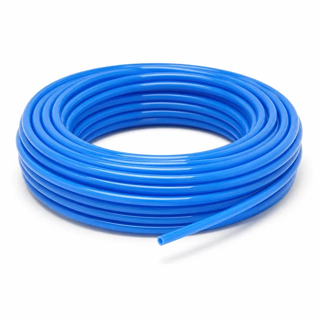
IMPORTANT: reference data — may differ from the physical product; verify with an advisor before buying.
SKU VT-142242 (nylon 12 tubing) · 14 diameter references, 4–16 mm and 1/4″–5/8″ · sold by 100 m roll or by the meter
1. Technical specifications
Dimensional data exactly as published in TECTUL's factory sheet for this tubing (file ft-mang-tubing-nylon.pdf). Wall thickness is not published directly: it is calculated here as (OD−ID)/2 from the two factory columns.
| Nominal OD | OD (mm / in) | ID (mm / in) | Calculated wall (mm / in) | Minimum bend radius (mm / in) |
|---|---|---|---|---|
| 4 mm | 4.0 / 0.157″ | 2.5 / 0.098″ | 0.75 / 0.030″ | 20 / 0.79″ |
| 4 mm | 4.0 / 0.157″ | 2.0 / 0.079″ | 1.00 / 0.039″ | 30 / 1.18″ |
| 5 mm | 5.0 / 0.197″ | 3.0 / 0.118″ | 1.00 / 0.039″ | 35 / 1.38″ |
| 6 mm | 6.0 / 0.236″ | 4.0 / 0.157″ | 1.00 / 0.039″ | 40 / 1.57″ |
| 8 mm | 8.0 / 0.315″ | 6.0 / 0.236″ | 1.00 / 0.039″ | 50 / 1.97″ |
| 10 mm | 10.0 / 0.394″ | 8.0 / 0.315″ | 1.00 / 0.039″ | 65 / 2.56″ |
| 10 mm | 10.0 / 0.394″ | 7.5 / 0.295″ | 1.25 / 0.049″ | 650 / 25.6″* |
| 12 mm | 12.0 / 0.472″ | 9.0 / 0.354″ | 1.50 / 0.059″ | 70 / 2.76″ |
| 16 mm | 16.0 / 0.630″ | 12.0 / 0.472″ | 2.00 / 0.079″ | 80 / 3.15″ |
| 1/4″ | 6.35 / 0.250″ | 4.35 / 0.171″ | 1.00 / 0.039″ | 38 / 1.50″ |
| 5/16″ | 7.94 / 0.313″ | 6.00 / 0.236″ | 0.97 / 0.038″ | 50 / 1.97″ |
| 3/8″ | 9.53 / 0.375″ | 7.50 / 0.295″ | 1.01 / 0.040″ | 60 / 2.36″ |
| 1/2″ | 12.70 / 0.500″ | 9.50 / 0.374″ | 1.60 / 0.063″ | 70 / 2.76″ |
| 5/8″ | 15.88 / 0.625″ | 11.87 / 0.467″ | 2.00 / 0.079″ | 125 / 4.92″ |
IMPORTANT
This technical data sheet is a reference guide to the properties of this product type; it is not a quality certificate for the product you are buying. The measurements, dimensions and physical or geometric characteristics of the product supplied may vary by manufacturer, heat and lot, and may even fall outside the cited standards. If any of these figures is critical to your design or build, verify it with one of our advisors against the physical product or the lot's mill certificate, so you can be fully certain of what you are buying. · Original data sheet: tectul.com/en/conduccion-de-fluidos/mangueras/ficha-tecnica-manguera-tubing-de-nylon-12-para-lineas-neumaticas.html
* The 650 mm radius is transcribed exactly as it appears in the factory sheet for the OD 10 mm/ID 7.5 mm row. In the other 13 rows the minimum radius runs 5 to 8 times the OD; following that pattern, a 10 mm OD tube would be expected around 60–80 mm, not 650 mm. The factory figure is reproduced unaltered because it is the only source available, but it is flagged for confirmation with the manufacturer before it is used in a routing design.
| Property | Value |
|---|---|
| Material | Nylon 12 (polyamide 12), single-wall extruded |
| Manufacturer-declared application | Pneumatic systems, robotics, industrial automation and instrumentation |
| Commercial presentation | 100-meter rolls (sold by the roll or by the meter depending on reference) |
| Working pressure per diameter | Not declared in this SKU's factory sheet — confirmed on quotation (see section 3 for general reference standards) |
| Manufacturer-declared service temperature | Not declared in this SKU's factory sheet — confirmed on quotation |
2. Engineering criterion: specified as tubing (OD), not as hose (ID)
Two different ways to name a diameter
A conventional hose (water, shop air, irrigation) is specified by its inner diameter (ID): the user picks a 1/2″ hose thinking of flow passage, and the outer diameter varies by manufacturer wall thickness. A tubing product like this one, instead, is specified by its outer diameter (OD), because OD is the dimension that determines which push-in fitting, gland or pneumatic connector it fits — the entire pneumatic fitting catalog (Prestolok, Festo, SMC type) is organized by OD, not ID. That is why the table in section 1 lists the nominal OD first (4, 5, 6, 8, 10, 12, 16 mm or 1/4″ to 5/8″): it is the figure that must match the fitting, not the air passage.
Semi-rigid, not braided
Single-wall nylon 12 is semi-rigid: it holds its shape on straight runs, is cut square with a tubing cutter (not a hose scissor) and inserts directly into push-in fittings with no clamp. A braided PVC or polyurethane hose, by contrast, is more flexible but needs a clamp or barbed fitting because its wall lacks the stiffness to seal on its own against an insertion fitting. That same stiffness is why the minimum bend radius in the table is not optional: forcing the tube below its minimum radius crushes it or cracks the wall, and with nylon 12 the damage is not always visible before it fails under pressure.
What this sheet does NOT say
This SKU's factory sheet does not publish a working pressure or service temperature per diameter — only dimensions and bend radius. Section 3 gathers the industry standards that do classify pressure and temperature for nylon 12 tubing, as general material context, without substituting for this specific reference's own figure (confirmed on quotation).
3. Normative classification: industrial pneumatic use, not approved air brakes
The same material, two different standard families
Single-wall nylon 12 (PA12) is the material behind two product families governed by different standards:
| Standard | Scope | Catalog reference range |
|---|---|---|
| DIN 73378 | General-purpose polyamide tubing: fuel lines, lubrication, compressed air and pneumatic systems in vehicles and industry | Catalog working pressure from manufacturers certified under this standard: on the order of 11 to 40 bar depending on diameter and wall thickness (third-party catalog value, not this reference's own) |
| SAE J844 | Nylon tubing specifically for commercial-vehicle air brakes (US), DOT-approved | Typical working pressure declared by the standard: 150 psi (10.3 bar); minimum burst on the order of 900–950 psi (62–65 bar); temperature range −40 °C to +93 °C (−40 °F to +200 °F) |
| ISO 7628-1 / DIN 74324 | Thermoplastic tubing for road-vehicle air braking systems (dimensions, marking and mounting) | Requires tube marking (manufacturer, standard, date) and mounting tests specific to brakes |
This TECTUL catalog reference is sold for general industrial pneumatic use (compressed air, automation, instrumentation), per its own factory sheet. It does not declare compliance with SAE J844, ISO 7628 or DIN 74324, the standards that require specific marking and testing for approved air brakes. DOT/ECE approval should not be assumed for this reference without confirming directly with the manufacturer.
What to check on the tube marking
Nylon 12 tubing compliant with any of these standards must carry legible, repeated printing along the roll: manufacturer, material (nylon 12 or PA12), and the reference standard where applicable. Missing marking makes it impossible to verify on site that the installed tube matches what was purchased, and is the first check point before installing on a system where traceability matters (instrumentation lines, for example).
4. Frequently asked questions
What is the working pressure of this nylon 12 tubing?
This reference's factory sheet does not declare a working pressure per diameter. As general material context, standards such as DIN 73378 classify nylon 12 tubing in third-party catalogs between 11 and 40 bar depending on diameter and wall thickness, and SAE J844 (for the specific case of air brakes) declares a 150 psi (10.3 bar) working pressure. Neither figure is this SKU's declared value: it is confirmed on quotation with the actual supplier.
What is the difference between the OD and ID in the table?
OD (outer diameter) is the dimension that must match the push-in fitting or pneumatic connector being used; ID (inner diameter) sets the available air passage. This tubing is ordered and fitted by OD, not by ID — unlike a conventional hose, which is ordered by ID.
Is this hose suitable for vehicle air brakes (DOT)?
That should not be assumed. This reference's factory sheet declares it for industrial pneumatic use (automation, instrumentation, compressed air), not for air brakes approved under SAE J844, ISO 7628 or DIN 74324, which require specific marking and testing this SKU does not declare.
What is the minimum bend radius for the 3/8″ diameter?
60 mm (2.36″), per the factory sheet. Installing the tube at a smaller radius crushes it or cracks the inner wall, damage that may not be visible before it fails under pressure.
Can it be used with water, or only compressed air?
The factory sheet only declares pneumatic application (compressed air, automation, instrumentation); it does not declare compatibility or working pressure for liquid conveyance. For use with liquids, chemical compatibility and pressure must be confirmed with the manufacturer before installing.
5. Application notes
Feasibility
This tubing is the solution for pneumatic compressed-air lines, automation and robotics where a semi-rigid tube that cuts square and inserts directly into push-in fittings is needed. It is not specified for approved air brakes (DOT/ECE) without confirming compliance with SAE J844/ISO 7628/DIN 74324, nor for pressure or temperature above what the manufacturer confirms on quotation, because the factory sheet does not declare those limits per diameter.
Installation
Always cut square with a tubing cutter, never at an angle with scissors or a knife: an angled cut will not seal in a push-in fitting. Respect the minimum bend radius from the section 1 table for each diameter; below that radius the tube crushes or cracks the inner wall with no damage visible from outside. Before installing in air brakes or any application requiring approval, confirm with the manufacturer whether this reference meets the required standard.
Design
Specify this tubing by its OD, not its ID, so it matches the chosen fitting. Do not assume a working pressure from general material standards (DIN 73378, SAE J844): they are contextual references, not this SKU's declared figure. For designs with elevated service temperature or pressure near the system limit, request the specific curve or value for this reference from the manufacturer before specifying it.
6. Technical notice and limitation of liability
The pressures, dimensions, weights and other characteristics in this sheet are theoretical calculation values obtained from nominal properties published in the standards cited (ASME B36.10-2022, ASME B31.3-2024, ASTM A106/A106M-19a, ASTM A53/A53M-24, API Spec 5L 46th ed.). They guide selection; they are not a certificate of conformity for any given lot.
The actual behavior of each lot varies with manufacturing — wall tolerance (up to −12.5%), out-of-roundness, residual stresses — and with the raw material — chemical composition within the ranges the standard allows, heat-to-heat differences. To certify a lot, the tests defined by its product standard are required: tensile test, flattening test and hydrostatic test, documented in the manufacturer's mill test certificate (MTC), which TECTUL supplies upon request; testing of the lot in an independent laboratory can also be arranged.
These values must not be used as the sole criterion in critical or safety applications, or wherever failure of the line may compromise people, property or the environment: in such cases the design belongs to the project's responsible engineer under the applicable code (ASME B31.3, B31.1 or the one governing the installation), with the design temperature, corrosion allowance and load cases of the actual service. Before deciding with these data, consult our technical team.
Sources
- Ficha técnica de fabricante (archivo interno TECTUL) — FT MANG TUBING NYLON (ft-mang-tubing-nylon.pdf): material nylon 12, tabla OD/ID/radio de curvatura mínimo por diámetro, aplicación y presentación por rollos de 100 m
- DIN 73378:1996 — Polyamide tubing for use in motor vehicles (tubing de poliamida monocapa para combustible, lubricación y aire comprimido; rangos de presión de catálogo de fabricantes certificados del orden de 11–40 bar según diámetro y espesor)
- SAE J844 — Nylon Air Brake Tubing (tubing de nylon para frenos de aire de vehículos comerciales; 150 psi de trabajo, reventamiento mínimo del orden de 900–950 psi, −40 °C a +93 °C)
- ISO 7628-1:2010 — Road vehicles — Thermoplastics tubing for air braking systems — Part 1: Dimensions and marking
- DIN 74324-1 — Polyamide tubing for air braking systems — Requirements and testing (basada en DIN 73378, añade requisitos específicos de frenos de aire)
This data sheet is the property of TECTUL, part of the Industrias IMR group. Reproduction without attribution is prohibited. Original document and updates: tectul.com/en/conduccion-de-fluidos/mangueras/ficha-tecnica-manguera-tubing-de-nylon-12-para-lineas-neumaticas.