 TECTULby IMR
Thermodynamic (disc) steam trap, with and without integral strainer — 1/2″ to 1″
TECTUL · Dispatch across Colombia · Exports to Central & South America
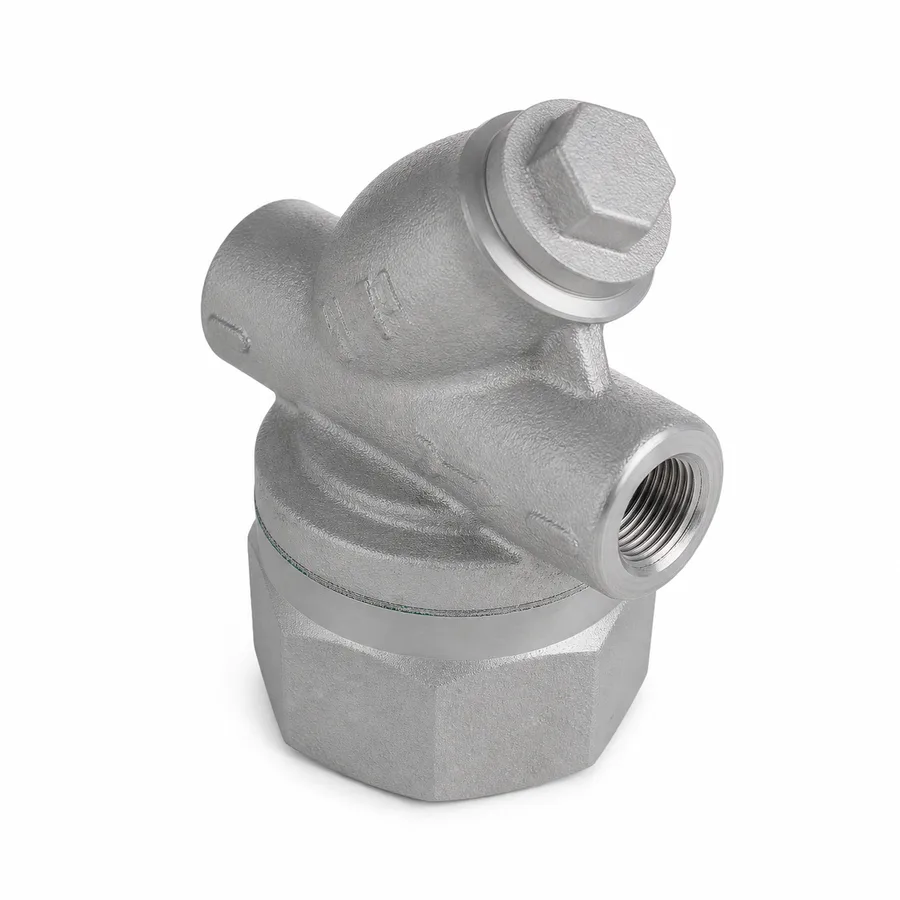
Single-disc thermodynamic steam trap from the TECTUL catalog, in two references — with an integral Y-type strainer and without — from 1/2″ to 1″, NPT threaded. It is the simplest trap on the market (a single moving part: a flat disc) and also the one that most demands discipline in reading its data sheet: the manufacturer marks the shell with a pressure and temperature rating (PMA/TMA) that is not the recommended operating pressure and temperature (PMO/TMO), and the mechanism stops closing reliably once the return-line back pressure exceeds roughly 80 % of the absolute inlet pressure. This sheet explains that quartet of acronyms, the Bernoulli physics that snaps the disc shut, the minimum operating pressure, the intermittent discharge cycle, the typical failure mode —open, blowing live steam— and the integral strainer on the reference that carries one.
Important: Before using these data in engineering, design or installation decisions on systems exposed to mechanical, pressure, rupture, fatigue, impact or water-hammer risk, it is essential to read the technical notice and limitation of liability at the end of this sheet.
SKU VT-87078 (thermodynamic trap with strainer) · 2 catalog references: with integral strainer and without, 1/2″ to 1″
1. Technical specifications
Materials by component and by reference
| Component | With strainer | Without strainer | Designation / source of the data |
|---|---|---|---|
| Body | Ductile (nodular) iron casting | Martensitic stainless steel | ASTM A536 (with strainer) · AISI 420 (without strainer), manufacturer data |
| Disc (single moving part) | Hardened stainless steel, flat disc | Same | Exact grade: manufacturer data |
| Seat (two concentric rings) | AISI 420 | AISI 410 | ASTM A276 (stainless steel bars and shapes, grades 410/420) |
| Cap (control chamber) | Threaded, with cooling fins to promote condensate cooling | Same | Manufacturer data |
| Integral strainer | Stainless steel mesh in a Y-type chamber integrated upstream of the seat, with a cleaning plug | Not applicable — requires an in-line strainer if the condensate carries solids | Mesh and cleaning procedure: manufacturer data |
| Ends | Female tapered NPT thread on both ends | ASME B1.20.1 | |
The manufacturer's sheet describes the strainer body as "stainless steel," but the designation it cites for that body is ASTM A536, which corresponds to ductile (nodular) iron casting, not a stainless steel: it is the same kind of catalog imprecision this series systematically corrects. The disc and seat are indeed stainless steel on both references.
References and sizes in the TECTUL catalog
| Reference | Sizes offered |
|---|---|
| Thermodynamic trap with strainer | 1/2″ · 3/4″ · 1″ |
| Thermodynamic trap without strainer | 1/2″ · 3/4″ · 1″ |
IMPORTANT
This data sheet is a reference guide to the properties of this product type. The measurements, dimensions and physical or geometric characteristics of the product actually supplied may vary by manufacturer and lot, and may even fall outside the cited standards. If any of these figures is critical to your design or build, it is essential to verify it with one of our advisors against the physical product, so you can be fully certain of what you are buying. · Original data sheet: tectul.com/en/conduccion-de-fluidos/valvulas/ficha-tecnica-trampa-termodinamica-con-filtro.html
Regulatory framework and supply conditions
| Trap type | Thermodynamic (disc): self-operated, driven by the pressure and velocity difference between steam and condensate, with no user-adjustable parts |
| Marking standard | ISO 6552 (standardized marking of automatic steam traps: PMA, TMA, PMO, TMO — see section 2) |
| Declared reference rating | 600 psi (41.4 bar) / 425 °C (797 °F), the only pair of values the manufacturer publishes for the strainer-less reference; taken as an approximation of the shell rating (PMA/TMA), not as a per-size certified PMO/TMO |
| Ends | Female NPT threaded per ASME B1.20.1 |
| Mounting orientation | Horizontal, cap facing up and body level, per the flow arrow cast on the body — the manufacturer sets the exact orientation per reference |
| Service fluid | Saturated water steam and its condensate; not suitable for gases incompatible with the stainless steel internals |
IMPORTANT
This data sheet is a reference guide to the properties of this product type. The measurements, dimensions and physical or geometric characteristics of the product actually supplied may vary by manufacturer and lot, and may even fall outside the cited standards. If any of these figures is critical to your design or build, it is essential to verify it with one of our advisors against the physical product, so you can be fully certain of what you are buying. · Original data sheet: tectul.com/en/conduccion-de-fluidos/valvulas/ficha-tecnica-trampa-termodinamica-con-filtro.html
Face-to-face dimensions, height and weight are not standardized for thermodynamic traps of this type — each manufacturer sets its own compact pattern — and are confirmed on quotation together with the factory PDF sheet.
⚠ Important: this technical data sheet is a reference guide to the product's properties; it is not a quality certificate for the product you are buying. Heats vary from one another and may differ from the values stated here, or even depart from the standards. If your application requires compliance with a standard, always check the quality certificate (mill certificate) of the lot you are buying. If in doubt, ask one of our technical advisors →
2. The PMA/TMA vs PMO/TMO quartet: how to read a steam trap data sheet
No commercial valve sheet in Spanish distinguishes these four values, and confusing them is the most common specification error in steam traps. The standardized marking system for steam traps, set out in ISO 6552, defines two pairs of figures that do not mean the same thing:
| Acronym | Meaning | What it describes |
|---|---|---|
| PMA | Maximum Allowable Pressure (of the shell) | The pressure the body and cap withstand without structural failure. It is a containment limit, analogous to a pressure vessel rating. |
| TMA | Maximum Allowable Temperature (of the shell) | The temperature the body material withstands without degrading. It is paired with PMA as a body-limit pair. |
| PMO | Maximum Operating Pressure (recommended) | The pressure up to which the internal mechanism —the disc, in this family— works reliably and repeatably. It is almost always lower than PMA. |
| TMO | Maximum Operating Temperature (recommended) | The saturated steam temperature matching PMO in normal service, not the material's destruction temperature. |
The reason for the difference is physical: the shell (body and cap) is a passive pressure envelope, while the disc is a mechanism that must open and close thousands of times without wearing out or losing its seating geometry. A high PMA certifies that the trap will not burst; it does not certify that the disc keeps cycling reliably at that same pressure. Specifying by PMA when the relevant figure is PMO is this family's most frequent reading error.
- It is the only value the manufacturer publishes for the strainer-less reference, and it is taken as an approximation of its PMA/TMA (shell rating), not as a per-size certified PMO/TMO.
- The actual PMO/TMO —the pressure and temperature up to which the disc cycles reliably in continuous service— is not published by the manufacturer for either reference in this sheet: it is confirmed on quotation with the factory PDF sheet.
- In industry practice, a thermodynamic trap's PMO is usually set below the shell's PMA, because disc and seat wear appear before the body approaches its containment limit.
- It must never be assumed that one reference's (or another size's) PMA applies as another's PMO: each body-disc-seat combination has its own pair of values.
The same PMA/TMA vs PMO/TMO pair applies, with the same logic, to the mechanical traps (float and inverted bucket) in data sheet FT-TC-VAL-TRAMPA-MEC-001 and to the shell of the steam reducing valves in section 5: it is the reading system for the catalog's entire steam line, not a peculiarity of this reference.
3. The 80 % rule: maximum back pressure and disc physics
Why the disc closes: the effect on its upper face
The thermodynamic trap has a single moving part: a flat disc that slides over two concentric rings machined into the seat (an inner one, the inlet; an outer one, leading out to the return line). When live steam or hot condensate already carrying flash steam enters at high velocity through the inner orifice, that velocity lowers the static pressure under the disc —the same principle described by the Bernoulli equation for flow through a restriction—. At the same time, a fraction of that flow leaks into the control chamber above the disc, where it loses velocity and regains pressure, and where part of the steam condenses against the cap. The result is a higher pressure above than below: that difference pushes the disc against the seat and keeps it closed, holding back the live steam.
The disc only reopens once the cap —exposed to ambient air and finned in many designs— cools the control chamber's content enough for the steam there to condense and the pressure to fall below what is pushing from underneath. At that instant, the accumulated condensate (already cold, with no flash) discharges in a pulse, and the cycle starts over.
The maximum back pressure rule
That physics depends on a pressure differential between the lower face and the control chamber. If the condensate return line —downstream of the trap— runs pressurized, that back pressure adds to the pressure under the disc and reduces the differential available to keep it closed. It is a design rule widely documented in thermodynamic trap practice: above roughly 80 % of the absolute inlet pressure, the differential is no longer enough for the disc to close reliably, and the trap can end up blowing live steam continuously or cycling erratically, instead of discharging only condensate.
- Inlet pressure (gauge): 6 bar (87 psi) — absolute pressure ≈ 7 bar (102 psia).
- Back pressure limit ≈ 80 % of 7 bar ≈ 5.6 bar absolute, i.e. ≈4.6 bar gauge in the return line.
- If the condensate line to the flash tank or header runs above that value, this reference is no longer the right choice: a mechanical trap (inverted bucket or float, sheet FT-TC-VAL-TRAMPA-MEC-001) should be evaluated, being less sensitive to back pressure.
The exact admissible back pressure percentage varies by disc design and manufacturer; the value in this section is the general rule for the thermodynamic family, documented in steam trap engineering practice. The specific admissible back pressure curve for each TECTUL catalog reference is confirmed on quotation.
4. Intermittent discharge, minimum pressure and typical failure mode
Discharge is intermittent, not continuous
Unlike a float trap —which can modulate an almost continuous discharge as condensate enters— the thermodynamic trap discharges in pulses: it closes, accumulates condensate while the control chamber cools, and snaps open to empty that accumulated volume. The frequency of those pulses depends on the condensate load and on how fast the cap cools: with a high load the interval between openings shortens; with a low load it lengthens. A regular metallic click from the trap is the normal acoustic evidence of the cycle; a much faster than usual rattle ("chatter"), nearly continuous, usually indicates disc or seat wear, excessive back pressure (section 3), or a trap oversized for the actual load.
Minimum operating pressure
The mechanism depends on the steam's velocity and pressure being enough to generate the differential that closes the disc (section 3). Below a minimum inlet pressure —specific to each disc and seat design— that differential is too weak: the trap can remain permanently partly open or cycle erratically even with no back pressure in the return line. This is why this family is not the typical choice for very low-pressure steam lines (for example, low-pressure steam heating under 0.5 bar gauge): the exact minimum pressure value per reference is set by the manufacturer and is confirmed on quotation.
Typical failure mode: open
Normal wear on a thermodynamic trap occurs on the disc's contact face and the seat rings, subjected to thousands of impact cycles and to erosion from high-velocity flash steam. That wear first degrades the disc's ability to seal completely against the outer ring, so that this family's characteristic failure mode is failing open: the trap ends up blowing live steam continuously or nearly continuously into the return line, rather than jamming shut (the more common failure mode in mechanical float traps when the mechanism seizes).
The cost of a failed-open trap is not obvious at a glance —the trap keeps "working," it is just letting live steam through on every cycle— and it translates directly into boiler fuel consumption: a failed-open 1/2" thermodynamic trap can waste an amount of steam comparable to that of several dozen healthy traps, sustained 24 hours a day. That is why steam plant maintenance programs include periodic acoustic or ultrasonic inspection of thermodynamic traps: it is the only economical way to catch a failed-open trap before the next energy audit.
5. The integral strainer: mesh, pressure drop and maintenance
What the strainer protects and why it sits ahead of the seat
The strainer reference incorporates a Y-type chamber upstream of the seat, with a removable stainless steel mesh accessed through a cleaning plug. Its function is to hold back scale, pipe rust, weld residue and other particles that would otherwise lodge between the disc and the seat rings —the thinnest and most wear-sensitive sealing surface in the whole trap— accelerating the wear that leads to the failed-open mode described in section 4. In new installations, where the piping still sheds mill scale and weld debris, the integral strainer reduces the risk of an early failure from a particle trapped under the disc.
Pressure drop and maintenance
Every mesh introduces an additional pressure drop, proportional to the mesh's open area and to the flow rate, which grows as the strainer retains particles and its effective area shrinks. That incremental pressure drop must be accounted for against the system's available differential pressure, especially in traps sized with little margin. The mesh opening, the recommended cleaning procedure and the interval between cleanings depend on the project's steam and condensate quality and are figures the manufacturer sets per reference.
When to choose the strainer-less reference
The strainer-less reference is the right choice when the line already has a Y-strainer installed upstream —a common practice when several traps share the same feed header— or in clean, already-run-in steam systems, where the risk of loose particles is low and the simpler maintenance of a body with no extra element to clean is preferred. In new systems, at plant start-up, or where there is no upstream strainer, the reference with a strainer reduces the risk of early failure and is this sheet's default choice.
6. Frequently asked questions
What pressure and temperature does this thermodynamic trap take?
The manufacturer declares 600 psi (41.4 bar) and 425 °C (797 °F) as the reference shell rating (an approximation of PMA/TMA) for the strainer-less reference. That value is not the recommended operating pressure and temperature (PMO/TMO): section 2 explains the difference, and the actual per-size PMO/TMO pair is confirmed on quotation.
Up to what back pressure does a thermodynamic trap work?
Up to roughly 80 % of the absolute inlet pressure. Above that point the pressure differential across the disc is no longer enough to close it reliably, and the trap can start blowing live steam into the return line. Details are in section 3.
Why does my thermodynamic trap "click" all the time?
The intermittent click of the disc is its normal way of operating: it closes, accumulates condensate, and snaps open to discharge it. A much faster than usual, nearly continuous rattle signals disc or seat wear, excessive back pressure, or oversizing against the actual load (section 4).
How does a thermodynamic trap fail as it wears?
This family's characteristic failure mode is open: the worn disc lets live steam through continuously or nearly continuously into the return line, rather than jamming shut. That lost steam is not obvious at a glance and translates into extra boiler fuel consumption; periodic acoustic inspection is therefore worthwhile.
With strainer or without?
With a strainer when the line is new, still shedding scale or weld debris, or has no Y-strainer installed upstream: it protects the disc and seat from particles that speed up failing open. Without a strainer when an upstream strainer already exists shared with other traps, or the system's steam and condensate are clean and run in.
Does this trap work for very low-pressure steam?
It is not the typical choice. Below a minimum inlet pressure specific to each design, steam velocity and pressure are not enough to generate the differential that closes the disc, and the trap can remain partly open or cycle erratically. The exact value is confirmed on quotation; for very low-pressure steam a mechanical trap is usually evaluated instead (sheet FT-TC-VAL-TRAMPA-MEC-001).
7. Application notes
Feasibility
This line covers saturated steam condensate in air venting, pipe tracing and main line drainage applications, with a declared reference rating of 600 psi (41.4 bar) / 425 °C. It is the natural choice in new installations or with dirty steam (strainer reference) and in already run-in lines with an upstream strainer (strainer-less reference). It is not the choice when the condensate return line runs pressurized above ≈80 % of the inlet pressure, when steam pressure is very low, or where near-continuous discharge modulation is required under a heat exchanger's variable load: in those cases evaluate the mechanical float trap (sheet FT-TC-VAL-TRAMPA-MEC-001). For critical or safety applications, consult our technical team before specifying.
Installation
Mount horizontally, cap facing up, following the flow arrow cast on the body, with clear access to remove the cap for maintenance. Install a shutoff valve upstream and, for the strainer-less reference, an upstream Y-strainer; install a check valve downstream if there is a risk of condensate returning from a common header. Verify that the return line's design back pressure stays below ≈80 % of the inlet pressure before confirming the selection (section 3). Do not enclose the trap in an unventilated box that prevents the cap from dissipating heat: cooling the control chamber is part of the operating cycle.
Design
Size by the equipment's actual condensate load and by the available differential pressure (inlet pressure minus return back pressure), not by the connecting pipe diameter. Verify the maximum admissible back pressure (≈80 % general rule, section 3) and the minimum operating pressure against the manufacturer's curve before confirming the reference. Remember that this sheet's 600 psi / 425 °C is a reference shell rating (approximate PMA/TMA), not the continuous-operation PMO/TMO (section 2): for service near the upper pressure or temperature limit, request the factory PDF sheet with the certified PMO/TMO pair. Include periodic acoustic or ultrasonic inspection in the predictive maintenance program: it is the economical way to catch this family's characteristic failed-open mode before it turns into extra boiler fuel consumption.
8. Technical notice and limitation of liability
The figures in this sheet combine the standardized ISO 6552 marking (definition of PMA, TMA, PMO and TMO) with the data the manufacturer declares on each product's sheet (600 psi / 425 °C for the strainer-less reference, sizes). The declared value is taken as an approximation of the shell rating (PMA/TMA); the actual continuous-operation PMO/TMO, the exact maximum admissible back pressure and the minimum operating pressure per reference are not published by the manufacturer and are confirmed on quotation with the factory certificate or PDF sheet.
The ≈80 % maximum back pressure rule in section 3 is a generalized design principle in thermodynamic trap practice, grounded in compressible flow physics (a Bernoulli-type effect on the control chamber), not a normative figure from a numbered standard table. The exact admissible value for each TECTUL catalog reference is confirmed on quotation. Face-to-face dimensions, height and weight are likewise not standardized for this family and depend on the actual manufacturer of each reference.
These values must not be used as the sole criterion in critical, safety applications, or wherever trap failure may compromise the process, people, property or the environment: in such cases sizing belongs to the project's responsible engineer, with the actual condensate balance, the line's differential pressure and the applicable code. Before deciding with these data, consult our technical team.
Sources
- ISO 6552 — Automatic steam traps — Marking: definición normalizada de PMA, TMA, PMO y TMO en la carcasa de trampas de vapor
- ASTM A536 — Standard Specification for Ductile Iron Castings: designación de fundición nodular citada por el fabricante para el cuerpo de la referencia con filtro
- ASTM A276/A276M — Standard Specification for Stainless Steel Bars and Shapes: grados AISI 410/420 usados en disco y asiento
- ASME B1.20.1 — Pipe Threads, General Purpose, Inch: rosca NPT de las conexiones
- Principios de mecánica de fluidos — ecuación de Bernoulli aplicada a flujo compresible a través de una restricción, fundamento físico del cierre del disco termodinámico y de la regla de contrapresión máxima
- NIST/ASME Steam Tables — propiedades termodinámicas del vapor de agua saturado y su condensado, base física del ciclo de apertura-cierre por temperatura
- Fichas de producto TECTUL (tectul.com): Trampa Termodinámica Con Filtro y Trampa Termodinámica Sin Filtro — fuente primaria de diámetros y del rating de referencia declarado (600 psi / 425 °C)
- Curaduría interna TECTUL (data/etapas/etapa-1-conduccion-de-fluidos/curaduria.json) — diámetros por referencia, agosto 2026
This data sheet is the property of TECTUL, part of the Industrias IMR group. Reproduction without attribution is prohibited. Original document and updates: tectul.com/en/conduccion-de-fluidos/valvulas/ficha-tecnica-trampa-termodinamica-con-filtro.html.