 TECTULby IMR
Mechanical steam traps: float with thermostatic air eliminator, and inverted bucket
TECTUL · Dispatch across Colombia · Exports to Central & South America
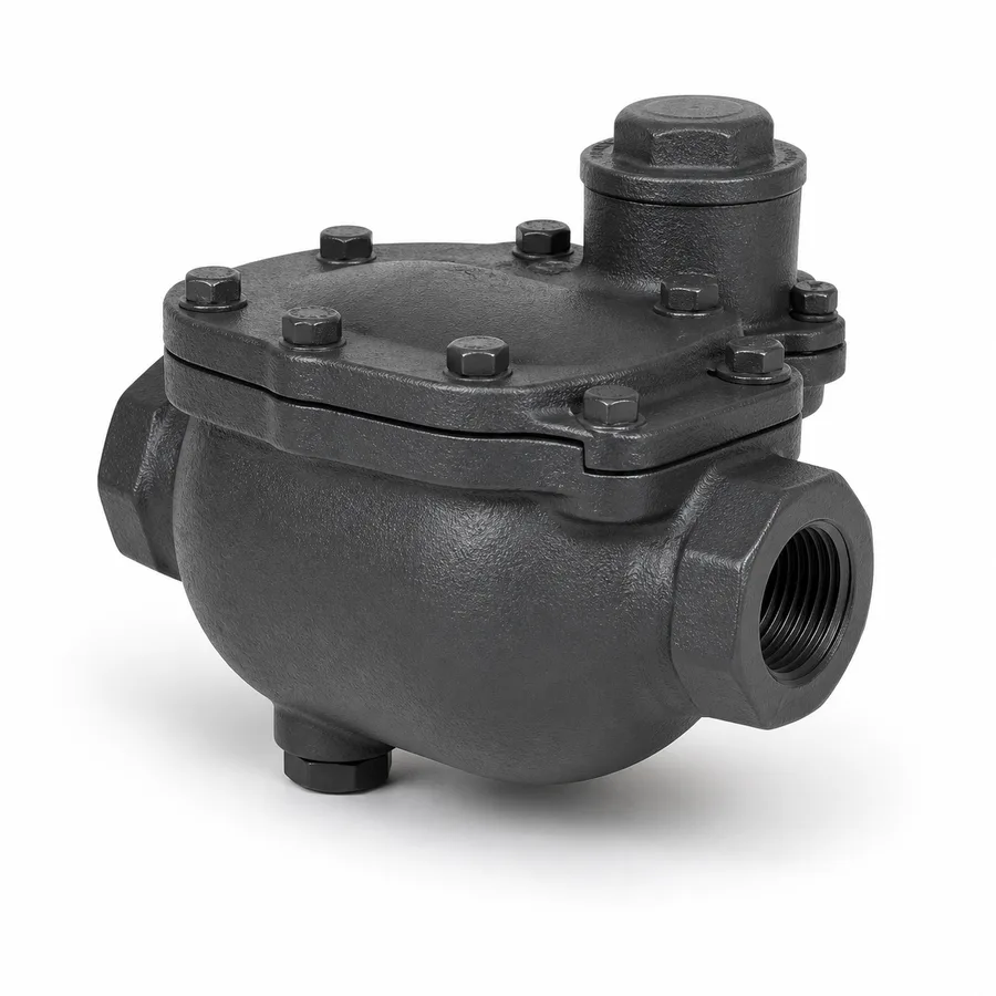
Two families of mechanical traps from the TECTUL catalog: the float trap, with a spherical or lever float that modulates condensate discharge almost continuously and an integral thermostatic air eliminator for start-up, and the inverted bucket trap, which uses an inverted metal bucket that floats or sinks depending on whether steam or condensate is underneath it, discharging intermittently. Both respond to the same general principle —a mechanical element that senses the fluid's density or level, unlike the thermodynamic (velocity/pressure) or thermostatic (temperature) trap— but they behave very differently under variable load, back pressure and water hammer. This sheet compares the three purging principles in a single table, explains when each mechanical design is the right choice, and develops the full sizing procedure by condensate load and real differential pressure.
Important: Before using these data in engineering, design or installation decisions on systems exposed to mechanical, pressure, rupture, fatigue, impact or water-hammer risk, it is essential to read the technical notice and limitation of liability at the end of this sheet.
SKU VT-trampa-vapor-flotador-termostato · 2 catalog references: float-and-thermostatic trap, and inverted bucket trap
1. Technical specifications
Float trap with thermostatic air eliminator
| Mechanism | Spherical or lever float linked to a needle valve; the condensate level inside the body raises or lowers the float, modulating the opening in direct proportion to the incoming flow rate |
| Air eliminator | A thermostatic element (capsule or bellows) independent of the float, which opens with cold air at start-up and closes once hot steam arrives — it vents start-up air without the float having to handle it |
| Discharge type | Modulated, practically continuous: the orifice adjusts to the actual flow rate at every instant, with no full open-close cycles |
| Service fluid | Saturated steam and its condensate; the thermostatic eliminator should not be exposed to sustained superheated steam without checking its range against the manufacturer |
| Ends | NPT threaded per reference; the exact variant's size and pressure are confirmed on quotation |
Inverted bucket trap
| Mechanism | Inverted metal bucket (mouth down) linked to a lever and a needle valve; steam trapped under the bucket makes it float and close the valve, condensate makes it sink and open it |
| Bucket venting | A calibrated orifice at the top of the bucket continuously bleeds a small amount of steam and air, preventing air binding — that vent is also this design's characteristic live-steam loss |
| Discharge type | Intermittent: the bucket must sink completely before opening the valve, producing a discharge pulse rather than continuous modulation |
| Robustness | Simple, robust mechanism against water hammer and moderate condensate dirt, valued on main steam distribution networks |
| Ends | NPT threaded per reference; the exact variant's size and pressure are confirmed on quotation |
Regulatory framework and supply conditions
| Trap type | Mechanical: operates by the fluid's physical state (level or density), with no user-adjustable parts beyond the bucket vent |
| Marking standard | ISO 6552 (standardized marking of automatic steam traps: PMA, TMA, PMO, TMO), the same standard governing sheet FT-TC-VAL-TRAMPA-TD-001 |
| Reference rating | The manufacturer does not publish PMA/TMA nor PMO/TMO for these two references in the current catalog: confirmed on quotation with the factory PDF sheet |
| Ends | Female NPT threaded per ASME B1.20.1 |
| Mounting orientation | Horizontal, body level per the manufacturer's marking; the inverted bucket additionally requires the body to be primed with water at first start-up (section 3) |
Face-to-face dimensions, height, weight and the per-reference size list are not standardized for this family and are not published by the manufacturer on the product page: they are confirmed on quotation together with the factory PDF sheet.
⚠ Important: this technical data sheet is a reference guide to the product's properties; it is not a quality certificate for the product you are buying. Heats vary from one another and may differ from the values stated here, or even depart from the standards. If your application requires compliance with a standard, always check the quality certificate (mill certificate) of the lot you are buying. If in doubt, ask one of our technical advisors →
2. The three purging principles in a single table
Every steam trap belongs to one of three families, according to which physical property of the fluid it uses to tell steam from condensate. It is the most useful selection framework in the entire steam line, and no commercial Spanish-language sheet publishes it in comparative form.
| Criterion | Mechanical (float / inverted bucket) | Thermodynamic (disc, sheet FT-TC-VAL-TRAMPA-TD-001) | Thermostatic (temperature-sensitive element) |
|---|---|---|---|
| Property sensed | Liquid level (float) or buoyancy/density (bucket) | Flow velocity and differential pressure | Fluid temperature |
| Discharge type | Float: modulated and near-continuous · Bucket: intermittent pulses | Intermittent pulses, single disc | Intermittent, opens with subcooled condensate |
| Back pressure tolerance | Float: high, nearly insensitive · Bucket: medium, sensitive to venting | Low: stops closing above ≈80 % of inlet pressure | Medium-high, depends on the element's range |
| Water hammer sensitivity | Bucket: low, robust mechanism · Float: medium, the float can be damaged by impact | Medium: the disc tolerates water hammer well but not wet steam with water carryover | Medium, depending on element construction |
| Typical failure mode | Float: jams closed if the mechanism seizes · Bucket: loses its seal and stays open (section 3) | Open (disc/seat wear) | Open or closed, depending on whether the element breaks expanded or contracted |
| Distinctive advantage | Float: follows variable load in real time, the best integrated air venting · Bucket: robust against dirt and water hammer | Simplicity (a single moving part), compact and economical | Subcools the condensate before discharging, better use of sensible heat |
Why the float trap is the right choice in variable-load heat exchangers
A heat exchanger, a heating coil or any process equipment whose steam demand rises and falls over the production cycle generates a condensate flow that varies continuously, not in pulses. The float trap is the only one of the three families that modulates its opening in proportion to the condensate level at every instant: it does not wait to fill completely before discharging, as the thermodynamic disc or the inverted bucket do. That modulation prevents condensate from backing up inside the equipment (waterlogging), which reduces the available heat transfer area and lowers the exchanger's thermal efficiency exactly when it is needed most, at load peaks.
The integral thermostatic air eliminator adds a second advantage for this service: during cold start-up, before steam arrives, the equipment is full of air, which is a poor heat conductor and which the float —sensitive only to liquid level— would not vent on its own. The thermostatic element, cold, stays open and lets that air out; once hot steam arrives it closes. That combination —float for condensate, thermostatic for air— is why this reference is the default trap in heat exchangers, not an arbitrary catalog preference.
3. Why the inverted bucket loses its seal with superheated steam or intermittent loads
The water seal is the mechanism's central piece
The inverted bucket floats or sinks depending on whether steam or condensate is trapped under its mouth, but that distinction only works if the trap body is full of water at start-up: it is the water surrounding the bucket that lets it float when steam is underneath and sink when denser condensate enters. An inverted bucket trap started dry —without priming the body with water before admitting steam— can end up with the bucket floating permanently and the valve closed, failing to vent the condensate that needs discharging from the very first minute.
Superheated steam: why it evaporates the seal
Superheated steam has a greater capacity to transfer heat to the surrounding water than saturated steam at the same pressure, precisely because it is not in thermal equilibrium with its liquid. If the trap operates under sustained superheated steam, that extra heat can evaporate the water surrounding the bucket before condensate replenishes it, leaving the bucket without the medium it needs to float or sink reliably: the mechanism loses its reference and behavior becomes erratic, typically staying open and blowing steam. For that reason the inverted bucket is designed for saturated steam or a low, sustained degree of superheat, not for lines with high or highly variable superheat.
Very intermittent loads: the same risk through another path
Equipment that consumes steam in short bursts separated by long no-flow periods subjects the trap to cooling cycles and possible seal loss through residual evaporation, followed by start-ups where the body may not be fully primed. It is the same failure mode —loss of the water seal— through a different cause than superheat: extreme intermittency instead of excess temperature. In both cases the result is the same: the bucket stops responding correctly to steam and condensate and the trap can end up blowing live steam.
The bucket's continuous venting: a design loss, not a failure
The vent orifice at the top of the bucket continuously bleeds a small amount of steam and air to prevent air binding. That small live-steam leak is inherent to the design, not a symptom of wear, and must be accounted for in the line's energy balance, especially in networks with many inverted bucket traps in continuous service.
When to choose an inverted bucket over a float: main steam distribution networks with possible water hammer and somewhat dirty condensate, where mechanical robustness outweighs fine modulation; never in high superheated-steam service nor in equipment with very frequent start-stop cycles, where a float with thermostatic air eliminator is the right choice.
4. Sizing: condensate load, safety factor and real differential pressure
The three data points that define the required capacity
Sizing a mechanical trap requires three data points, none of which is the connecting pipe diameter:
- Real condensate load (kg/h): the condensate flow rate generated by the equipment in normal operation, calculated from the process steam consumption or measured directly. It is not a trap catalog figure: it comes from the upstream equipment.
- Safety factor: the normal load is multiplied by a factor —typically between 2 and 3 times in mechanical trap sizing practice— to cover cold start-up peaks, when the equipment simultaneously purges the condensate accumulated during shutdown and the start-up air, generating a demand several times greater than in steady state.
- Real differential pressure: not the inlet pressure alone, but
ΔP = inlet pressure − return line back pressure. Any trap's discharge capacity falls as that differential shrinks, and a trap sized only from inlet pressure without subtracting back pressure ends up undersized in practice.
- Equipment data: heat exchanger consuming saturated steam at 6 bar (87 psi) gauge, with a nominal consumption generating a normal condensate load of 350 kg/h.
- Apply the safety factor: with a 2.5× factor (cold start-up with simultaneous purging of accumulated condensate and air), the trap's required discharge capacity is 350 kg/h × 2.5 = 875 kg/h.
- Determine the real differential pressure: the condensate return line to the flash tank runs at 1.5 bar (22 psi) gauge back pressure. The available differential pressure is ΔP = 6 bar − 1.5 bar = 4.5 bar (65 psi), not the 6 bar at the inlet.
- Select the trap: look up, on the manufacturer's capacity curve, the reference and size whose discharge capacity at 4.5 bar differential —not at 6 bar— is equal to or greater than 875 kg/h. Using the 6 bar curve in this example would overestimate the actual available capacity and leave the trap undersized against the line's real back pressure.
- Verify the mechanism against the service: if the equipment is a heat exchanger with variable demand during the process, the float-and-thermostatic reference is the right one (section 2); if the line has water hammer and the condensate carries some dirt and the steam is not superheated, the inverted bucket is a valid alternative (section 3).
The 2-to-3-times safety factor is a generalized sizing practice in mechanical trap engineering, not a value from a numbered standard table; adjust it to the equipment's actual cold start-up severity. The capacity curve (kg/h as a function of size and pressure differential) for each TECTUL catalog reference is confirmed on quotation with the factory PDF sheet.
5. Frequently asked questions
Float trap or inverted bucket?
Float with thermostatic eliminator in heat exchangers and process equipment with variable load: it modulates discharge in real time and vents start-up air well. Inverted bucket on main distribution networks with water hammer and somewhat dirty condensate, provided the steam is not superheated and the service is not very frequent start-stop. The comparative table in section 2 summarizes the differences.
Why did my inverted bucket trap stop working after a superheated steam spike?
Because sustained superheated steam can evaporate the water seal surrounding the bucket before condensate replenishes it: without that seal the bucket no longer reliably tells steam from condensate and the mechanism becomes erratic, typically staying open. Details are in section 3.
How is a mechanical trap's capacity calculated?
From the equipment's real condensate load, multiplied by a 2-to-3-times safety factor to cover cold start-up, and read on the manufacturer's curve against the real differential pressure —inlet pressure minus return back pressure, not inlet pressure alone. Section 4 develops a complete worked example.
Can an inverted bucket trap be started without priming the body with water?
Not recommended. The mechanism depends on the body being full of water for the bucket to float or sink reliably; started dry, the bucket can end up floating permanently with the valve closed, failing to vent the condensate that must be discharged from start-up.
Which of the two mechanical traps tolerates back pressure better?
The float tolerates back pressure much better than the inverted bucket and than the thermodynamic trap: its level-based modulation does not depend on a velocity differential like the thermodynamic disc. The bucket is more sensitive because its continuous venting and floating cycle are affected if the return line runs highly pressurized. The exact value per reference is confirmed on quotation.
What happens if I size the trap only by inlet pressure, without subtracting back pressure?
The trap ends up undersized in practice: its real discharge capacity depends on the available differential pressure, which is lower than the inlet pressure as soon as the return line runs pressurized. The example in section 4 shows how to correctly calculate that differential before selecting the reference.
6. Application notes
Feasibility
The float-and-thermostatic trap covers heat exchangers, coils and process equipment with variable condensate load, where continuous modulation prevents equipment waterlogging. The inverted bucket trap covers main steam distribution networks with water hammer and somewhat dirty condensate, in saturated steam service or with low, sustained superheat. Out of scope: high or highly variable superheated steam and very frequent start-stop service for the inverted bucket (section 3); lines where back pressure reduces the available differential too much without verifying the real capacity curve (section 4). For critical or safety applications, consult our technical team before specifying.
Installation
Mount with the body level per the manufacturer's marking, with clear access for maintenance of the internal mechanism. On the inverted bucket trap, prime the body with water before admitting steam for the first time (section 3): a dry start-up can leave the bucket floating permanently. Install a shutoff valve upstream and, if the condensate carries particles, a Y-strainer; install a check valve downstream if there is a risk of return from a common header. Verify the installation's real differential pressure —inlet minus back pressure— against the capacity curve before confirming the reference (section 4).
Design
Select the mechanical principle by service: float and thermostatic for the variable load of heat exchangers, inverted bucket for main networks with water hammer and non-superheated steam (sections 2 and 3). Size by the real condensate load multiplied by a 2-to-3-times safety factor, and verify capacity against the real differential pressure —inlet minus return back pressure—, not against inlet pressure alone (section 4, with a complete worked example). Request the factory capacity curve (kg/h vs. size and differential) and the PMO/TMO pair before closing the specification for services near pressure or temperature limits.
7. Technical notice and limitation of liability
This sheet combines the three-principle steam trap framework (mechanical, thermodynamic, thermostatic), the standardized ISO 6552 marking (PMA/TMA/PMO/TMO) and the data TECTUL publishes on each product's page (mechanism description). The manufacturer does not publish PMA/TMA, PMO/TMO or a capacity curve (kg/h vs. differential pressure) for these two references in the current catalog: they are confirmed on quotation with the factory PDF sheet or certificate.
The 2-to-3-times safety factor and the real differential pressure = inlet − back pressure rule in section 4 are generalized sizing practices in mechanical trap engineering, backed by the process condensate balance, not figures from a numbered standard table. Adjust the factor to the specific equipment's real cold start-up severity. Face-to-face dimensions, height, weight and the per-reference size list are likewise not standardized for this family and depend on the actual manufacturer of each reference.
These values must not be used as the sole criterion in critical, safety applications, or wherever trap failure may compromise the process, people, property or the environment: in such cases sizing belongs to the project's responsible engineer, with the real condensate balance, the line's transients and the applicable code. Before deciding with these data, consult our technical team.
Sources
- ISO 6552 — Automatic steam traps — Marking: definición normalizada de PMA, TMA, PMO y TMO, común a toda la línea de vapor del catálogo
- ASME B1.20.1 — Pipe Threads, General Purpose, Inch: rosca NPT de las conexiones
- NIST/ASME Steam Tables — propiedades termodinámicas del vapor saturado y sobrecalentado: base física de la pérdida del sello de agua del balde invertido bajo sobrecalentamiento
- Principios de mecánica de fluidos e hidrostática — flotación y densidad aplicadas al balde invertido y al flotador; el mismo marco que sustenta la física del disco termodinámico en la ficha FT-TC-VAL-TRAMPA-TD-001
- Práctica generalizada de dimensionamiento de purgadores mecánicos — factor de seguridad de 2 a 3 veces sobre la carga normal de condensado para cubrir el arranque en frío, documentada de forma consistente en la ingeniería de sistemas de vapor
- Fichas de producto TECTUL (tectul.com): Trampa de Vapor Flotador y Termostato, y Trampa de Vapor Balde Invertido — fuente primaria de la descripción del mecanismo
- Curaduría interna TECTUL (data/etapas/etapa-1-conduccion-de-fluidos/curaduria.json) — referencias, agosto 2026
This data sheet is the property of TECTUL, part of the Industrias IMR group. Reproduction without attribution is prohibited. Original document and updates: tectul.com/en/conduccion-de-fluidos/valvulas/ficha-tecnica-trampa-vapor-flotador-termostato.html.