 TECTULby IMR
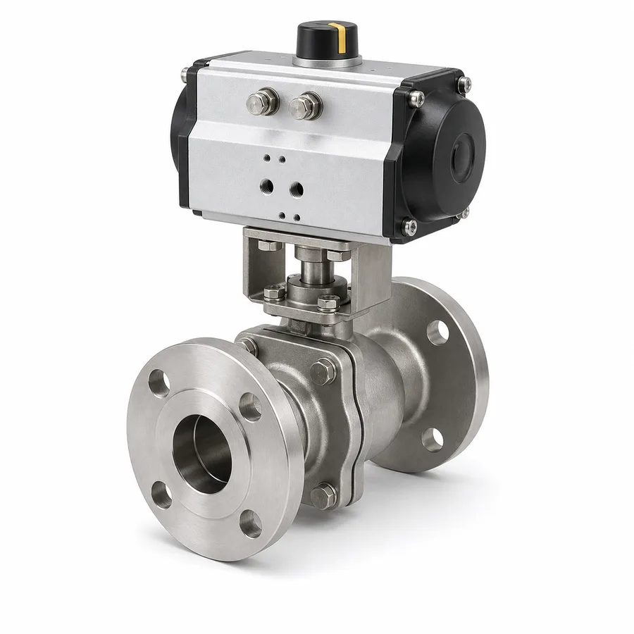
Automated flanged and stainless ball valve — ISO 5211 interface with pneumatic or electric actuator
TECTUL · Dispatch across Colombia · Exports to Central & South America
Automation layer over the TECTUL catalog's flanged, stainless and three-way ball valve: direct mounting of a pneumatic or electric quarter-turn actuator per the ISO 5211 interface, selected by the valve's operating torque rather than by its size. This sheet gathers what the base valve sheets (FT-TC-VAL-BOLAB-CARBON-001 and FT-TC-VAL-BOLAB-INOX-001) do not cover: the ISO 5211 mounting table by flange type (F03 to F14) with its maximum torque, the technical selection table between pneumatic and electric actuators (available torque, operating time, power supply, fail behavior, cycles and environment), the reference pneumatic pilot pressure, the port configurations of the three-way valve (L and T, diverting versus mixing) and the automation accessories — solenoid pilot valve, limit switch box and positioner.
Important: Before using these data in engineering, design or installation decisions on systems exposed to mechanical, pressure, rupture, fatigue, impact or water-hammer risk, it is essential to read the technical notice and limitation of liability at the end of this sheet.
SKU VT-valvula-bola-bridada-actuador-neumatico · line of 6 automated references: flanged, stainless and three-way, each with a pneumatic or electric actuator
1. Technical specifications
Base valve and scope of this sheet
This sheet covers the automation layer: the actuator and its mounting interface. The ball valve itself —body material, pressure-temperature rating, ends and dimensions— corresponds to this same family's type sheets: FT-TC-VAL-BOLAB-CARBON-001 (carbon steel WCB) or FT-TC-VAL-BOLAB-INOX-001 (stainless steel CF8M), depending on the reference's material. The six catalog references covered here —flanged, stainless and three-way, each with a pneumatic or electric actuator— share a stainless steel body per their commercial sheet, with class 150 flanged ends (ASME B16.5) on the flanged variants and ISO 5211 mounting on all of them.
ISO 5211 mounting interface by flange type
| Type | Bolt circle Ø (d3) | Pilot/spigot Ø (d2) | Number and thread of bolts | Maximum allowable torque |
|---|---|---|---|---|
| F03 | 36 mm | 25 mm | 4 × M5 | 32 N·m |
| F05 | 50 mm | 35 mm | 4 × M6 | 125 N·m |
| F07 | 70 mm | 55 mm | 4 × M8 | 250 N·m |
| F10 | 102 mm | 70 mm | 4 × M10 | 500 N·m |
| F12 | 125 mm | 85 mm | 4 × M12 | 1,000 N·m |
| F14 | 140 mm | 100 mm | 4 × M16 | 2,000 N·m |
IMPORTANT
This data sheet is a reference guide to the properties of this product type. The measurements, dimensions and physical or geometric characteristics of the product actually supplied may vary by manufacturer and lot, and may even fall outside the cited standards. If any of these figures is critical to your design or build, it is essential to verify it with one of our advisors against the physical product, so you can be fully certain of what you are buying. · Original data sheet: tectul.com/en/conduccion-de-fluidos/valvulas/ficha-tecnica-valvula-bola-bridada-actuador-neumatico.html
Dimensions per ISO 5211 (the international standard for the mounting interface of quarter-turn actuators): bolt circle, centering spigot diameter and maximum torque each flange type admits, independent of the actuator brand. The valve's shaft (square or rectangular depending on the flange) transmits the actuator's torque to the ball.
Indicative reference from DN to ISO 5211 flange type
| Approximate nominal size | Usual flange type |
|---|---|
| 1/2″ – 1″ (DN 15–DN 25) | F04 / F05 |
| 1-1/4″ – 1-1/2″ (DN 32–DN 40) | F05 / F07 |
| 2″ (DN 50) | F07 |
| 2-1/2″ – 3″ (DN 65–DN 80) | F07 / F10 |
| 4″ (DN 100) | F10 / F12 |
| 6″ (DN 150) | F12 / F14 |
| 8″ (DN 200) and larger | F14 or higher (outside this table) |
IMPORTANT
This data sheet is a reference guide to the properties of this product type. The measurements, dimensions and physical or geometric characteristics of the product actually supplied may vary by manufacturer and lot, and may even fall outside the cited standards. If any of these figures is critical to your design or build, it is essential to verify it with one of our advisors against the physical product, so you can be fully certain of what you are buying. · Original data sheet: tectul.com/en/conduccion-de-fluidos/valvulas/ficha-tecnica-valvula-bola-bridada-actuador-neumatico.html
This correspondence is indicative, not a standard rule. The real flange type is defined by the valve's operating torque at that differential pressure, not by size alone: two valves of the same DN can require different ISO 5211 flanges depending on the seat design, the service pressure and whether the actuator is single- or double-acting. The exact torque of each figure and its corresponding ISO 5211 flange are confirmed on quotation with the actuator data sheet.
⚠ Important: this technical data sheet is a reference guide to the product's properties; it is not a quality certificate for the product you are buying. Heats vary from one another and may differ from the values stated here, or even depart from the standards. If your application requires compliance with a standard, always check the quality certificate (mill certificate) of the lot you are buying. If in doubt, ask one of our technical advisors →
2. Technical selection: pneumatic versus electric actuator
The choice between pneumatic and electric is not a matter of preference but of available infrastructure, operating frequency and required fail behavior. This table summarizes the selection criteria; the educational why behind each mechanism belongs to the catalog's educational content — here are the engineering figures needed to specify.
| Criterion | Pneumatic actuator | Electric actuator |
|---|---|---|
| Power supply | Plant compressed air, typically 4–8 bar (60–116 psi) | 110/220 VAC or 24 VDC depending on model |
| Operating time (90°) | Fast, typically 1 to 5 seconds | Slower, typically 15 to 60 seconds or more, adjustable on variable-speed models |
| Behavior on loss of supply | Single-acting (spring): returns to a predefined safe position (fail-close or fail-open) with no external energy. Double-acting: stays in the last position — not fail-safe on its own | Stays in the last position (fails as-is); fail-safe requires a backup battery or mechanical spring, a less common, more complex option |
| Operating cycles | Very high cycle count, suited to frequent switching | Limited by the motor and its duty cycle — not suited to very frequent switching without a heavy-duty motor |
| Precision and modulation | Requires a positioner (section 4) to modulate; on its own it is on/off | With position feedback (potentiometer or encoder) it can modulate more natively |
| Environment / IP | IP66/IP67 enclosures typical; no electrical hazard in the actuator itself | IP66/IP67 and, in certified versions, explosion-proof (Ex d) for classified areas |
| Infrastructure requirement | Requires a compressed air line at the mounting point | Requires an electrical supply at the mounting point |
| Typical use | Fast shut-off, high cycle frequency, plants with existing air network | Remote locations with no compressed air, infrequent operation, position-feedback control |
General industry-practice ranges for quarter-turn actuators; the exact operating time, air or current consumption and area classification depend on the model and are confirmed with the actuator data sheet on quotation.
Actuator selection safety factor
The actuator is selected by the largest of the valve's three torque values —breakaway, running and end/seating— in each direction of rotation, multiplied by a safety factor: 1.5× is standard industry practice; it is raised to 2.0× in severe service (high temperature, erosive or corrosive fluid) or when the valve stays static for long periods between operations, because breakaway torque after prolonged inactivity is usually higher than nominal. Reducing the factor below 1.5× is a conscious engineering decision, not a default shortcut.
- The valve requires, per its torque data sheet, a breakaway torque of 40 N·m and a running torque of 25 N·m.
- Take the larger one: 40 N·m.
- Apply the standard safety factor: 40 N·m × 1.5 = 60 N·m as the actuator's minimum output.
- With that figure, look up in the section 1 table the ISO 5211 flange type whose maximum torque covers it with margin: in this example, F10 (500 N·m) meets it with plenty of room, while F05 (125 N·m) would also work — the actuator and its flange are selected by that actuator model's real torque, not just by the minimum required.
The real breakaway and running torque of each TECTUL catalog figure is published by the actuator manufacturer and confirmed on quotation: there is no single figure for "a ball valve of such-and-such size", because it depends on the seat design, differential pressure and the valve's condition.
3. Three-way valve configurations: L-port and T-port
This family's automated three-way ball valve uses an L-bored or T-bored closure member. The difference is not in material or torque but in which port combinations remain connected at each position of the 90° rotation (or of two 90° rotations in the four-position design).
| Port type | Ports connected per position | Function | Typical use |
|---|---|---|---|
| L (diverting) | At each position, exactly two of the three ports are connected to each other; the third stays closed. It never connects all three at once. | Selector / diverter: routes flow from a common port to one of two destinations, exclusively | Alternating supply between two lines or two pieces of equipment without mixing the flows |
| T (mixing or diverting) | Includes the same diverting positions as the L port plus one additional position in which all three ports are connected simultaneously | Mixer or diverter with the ability to combine two flows into a single outlet port | Mixing two inlet flows into a single outlet line, or splitting one inlet flow between two outlets at the same time |
General L-port and T-port nomenclature used across multi-way ball valves; the exact position of each figure (marked on the lever or on the actuator indicator) is set by the manufacturer and must be verified before start-up, because a wrong reading of the position can mix two fluids that were meant to stay separate.
Selection rules
- If the process requires that the two flows never mix with each other (only alternating one destination), the L port is the correct design: it has no triple-communication position.
- If the process needs to combine or split simultaneously, the T port allows it; verify with the manufacturer whether that intermediate mixing position is the rotation's center position or an additional discrete position, since it varies by design.
- A three-way valve introduces more pressure drop and more complex flow geometries than a two-way valve of the same size: hydraulic sizing must consider the fluid's real path inside the L or T body, not just the nominal diameter.
- The actuator of a T-port three-way valve normally requires extra torque at the mixing position due to greater contact between the closure member and the flow; the manufacturer's data sheet torque already accounts for this condition and is what is used for the section 2 selection, not a generic estimate.
4. Automation accessories: solenoid, limit switches and positioner
Solenoid pilot valve (pneumatic actuator)
Converts an electrical signal into air routing to the actuator's chambers. On a single-acting (spring-return) actuator, a 3/2 pilot solenoid valve (three ports, two positions) is used: energized, it admits air and compresses the spring; de-energized, it releases the air and the spring returns the valve to its safe position. On a double-acting actuator, a 5/2 valve (five ports, two positions) is used, directing air alternately to each chamber to open and close; with no return spring, loss of signal leaves the valve in its last position. Usual coil voltage 24 VDC or 110/220 VAC; classified areas require an explosion-proof version.
Limit switch box
Remotely indicates whether the valve is in the open or closed position, via microswitches or proximity sensors triggered by adjustable cams coupled to the actuator shaft. It mounts between the actuator and the valve or directly on the actuator, depending on the brand; usual enclosure IP66/IP67, with an explosion-proof option. It is the accessory that enables remote position monitoring in a control system (DCS/PLC) without local visual inspection.
Positioner
Receives a continuous control signal (usually 4-20 mA or pneumatic 3-15 psi) and adjusts the actuator's angular position proportionally, rather than just on/off. It is the accessory added when the process requires flow modulation with this automated valve; it is worth remembering that a ball, as a shut-off device, is not the first choice for fine flow modulation — if the control point requires continuous, precise regulation, evaluate whether a dedicated control valve is more suitable before forcing modulation onto a ball valve with a positioner.
Scope of the valve's own certification
The accessories in this section are selected and certified independently from the valve: the classified-area certificate (Ex d, Ex ia, etc.) and the IP rating belong to the actuator and its accessories, not to the mechanical valve itself. They are confirmed on quotation according to the project's area classification.
5. Frequently asked questions
How do I know what ISO 5211 flange my valve needs?
By the valve's operating torque, not by its size: take the largest torque among breakaway, running and end/seating, multiply it by the safety factor (1.5× in standard service), and choose the flange type (F05 to F14) whose maximum torque covers that figure with margin, per the section 1 table. This sheet's DN-to-flange correspondence is only indicative.
Is the pneumatic actuator fail-safe?
Only if it is single-acting with a spring: on loss of air or signal, the spring returns the valve to a predefined position (fail-close or fail-open) with no external energy. A double-acting actuator stays in its last position on loss of air — it is not fail-safe on its own.
What air pressure does the pneumatic actuator need?
Between 4 and 8 bar (60–116 psi) depending on the model, with a usual design point between 5.5 and 6 bar. The actuator must be sized using the minimum expected pressure of the air network, not the nominal one, to avoid losing torque in the worst case.
What is the difference between the L port and the T port of a three-way valve?
The L port never connects all three ports at once: at each position it connects only two, useful for diverting flow without mixing. The T port also includes a position where all three ports are connected simultaneously, useful for mixing two flows into one outlet or splitting one into two.
Do I need a positioner for this valve?
Only if the process requires continuous flow modulation, not simple open/close. In that case, first evaluate whether a dedicated control valve is more suitable: a ball valve is a shut-off device, and forcing fine modulation onto it with a positioner has precision and wear limits that a control valve designed for that function does not have.
6. Application notes
Feasibility
The automation layer covers remote shut-off, PLC/DCS-controlled sequences and, with a positioner, approximate flow modulation, within the maximum torque of the selected ISO 5211 flange and the air pressure available on the pneumatic unit or the electrical supply on the electric one. Out of scope: fine, continuous flow modulation as the primary function, for which a dedicated control valve is the right choice; and operation in a classified area without verifying the specific certification of the actuator and its accessories, which is managed separately from the mechanical valve. For critical or safety applications, consult our technical team before specifying.
Installation
Check the valve's torque against the actuator's torque before coupling, with the section 2 safety factor already applied. Align the shaft and the ISO 5211 centering spigot before bolting; tighten the actuator flange bolts in a cross pattern, like any bolted joint. On pneumatic units, purge and filter the supply air before connecting, to avoid introducing moisture or particles into the solenoid or the actuator. On electric units, verify voltage and area classification before energizing. On three-way valves, physically confirm the port position (L or T) against the project drawing before start-up: a misidentified position can mix fluids that were meant to stay separate.
Design
Specify the actuator by the valve's real torque (breakaway, running and end/seating, in both directions), multiplied by the safety factor, not by a generic size-based rule. Define from the project stage whether the application requires fail-safe behavior (pneumatic spring or electric battery/spring) and state it in the specification, because it changes the required actuator type. If the line is three-way, define whether the process allows a mixing position (T port) or requires total exclusion (L port) before ordering the reference. For modulation, evaluate a dedicated control valve first before forcing a positioner onto this ball valve. The pressure-temperature rating, materials and dimensions of the base valve are defined by the corresponding type sheet (FT-TC-VAL-BOLAB-CARBON-001 or FT-TC-VAL-BOLAB-INOX-001), not by this sheet.
7. Technical notice and limitation of liability
The mounting interface dimensions in this sheet follow ISO 5211 (bolt circle, centering spigot and maximum torque per flange type). The pressure-temperature rating, materials and dimensions of the base mechanical valve belong to the FT-TC-VAL-BOLAB-CARBON-001 and FT-TC-VAL-BOLAB-INOX-001 sheets depending on the reference's material; this sheet does not repeat them and must not be read as an independent source for that data.
The 1.5× (up to 2.0×) safety factor on the valve's torque is general practice in valve automation, not a single-standard figure; the 4-8 bar pneumatic pilot pressure and operating times are usual industry-practice ranges. The real breakaway, running and end/seating torque of each figure, its corresponding ISO 5211 flange and the classified-area certification of the actuator and its accessories are published and certified by the actuator manufacturer, and are confirmed on quotation.
These values must not be used as the sole criterion in critical or safety applications, service in a classified area without verified certification, or wherever failure of the valve or actuator may compromise people, property or the environment: in such cases the design belongs to the project's responsible engineer. Before deciding with these data, consult our technical team.
Sources
- ISO 5211:2017 — Industrial valves — Part-turn actuator attachments: tipos de brida F03 a F14, círculo de pernos, resalte de centrado y par máximo admisible por tipo
- ASME B16.5-2020 — Pipe Flanges and Flanged Fittings: extremos bridados clase 150 de las variantes bridadas de esta línea
- API 608 — Metal Ball Valves: Flanged, Threaded, and Welding Ends: diseño base de la válvula de bola sobre la que se monta el actuador
- Práctica industrial de selección de actuadores de cuarto de vuelta: factor de seguridad de 1,5× a 2,0× sobre el par de arranque/operación/asentamiento, tomando el mayor de los tres valores en cada sentido
- Rangos de práctica industrial de actuadores neumáticos y eléctricos: presión de pilotaje de 4-8 bar (60-116 psi), tiempos de maniobra, IP y clasificación de área, consistentes con catálogos de fabricantes de actuadores de cuarto de vuelta
- Nomenclatura general de puerto L y puerto T de válvulas de bola multivía, de uso consistente entre fabricantes de válvulas de tres vías
- Fichas técnicas TECTUL FT-TC-VAL-BOLAB-CARBON-001 y FT-TC-VAL-BOLAB-INOX-001 — fuente del rating, materiales y dimensiones de la válvula base sobre la que se monta esta capa de automatización
- Fichas de producto TECTUL (tectul.com): las seis referencias bridada/inoxidable/tres vías con actuador neumático o eléctrico — fuente primaria de material declarado
This data sheet is the property of TECTUL, part of the Industrias IMR group. Reproduction without attribution is prohibited. Original document and updates: tectul.com/en/conduccion-de-fluidos/valvulas/ficha-tecnica-valvula-bola-bridada-actuador-neumatico.html.