 TECTULby IMR
Threaded bronze gate valves, ASTM B62 C83600 — dual SWP/WOG classes (MSS SP-80)
TECTUL · Dispatch across Colombia · Exports to Central & South America
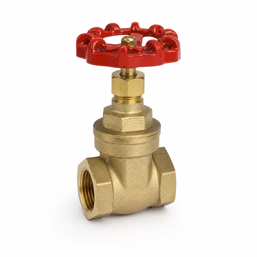
Two NPT threaded gate valve references in ASTM B62 C83600 cast bronze (85-5-5-5 alloy) from the TECTUL catalog, with solid wedge, bronze stem and screw, ASTM B16 C36000 brass gland, asbestos-free PTFE packing and ASTM A536 ductile iron handwheel. Nine sizes per reference, 1/2″ to 4″ (DN 15 to DN 100), tapered NPT threaded ends per ASME B1.20.1. This sheet develops the rating system that governs the family — the MSS SP-80 dual SWP/WOG classes — and why a gate valve is a full-shutoff device that must not be operated partially open.
Important: Before using these data in engineering, design or installation decisions on systems exposed to mechanical, pressure, rupture, fatigue, impact or water-hammer risk, it is essential to read the technical notice and limitation of liability at the end of this sheet.
SKU VT-59207 (Napoli bronze gate valve) · 2 bronze gate references, 9 sizes each from 1/2″ to 4″
1. Technical specifications
Materials by component
| Component | Material | Designation / standard |
|---|---|---|
| Body and bonnet | Cast bronze, 85-5-5-5 alloy (84–86 % Cu, 4–6 % Sn, 4–6 % Pb, 4–6 % Zn) | ASTM B62, alloy C83600 |
| Closure member (solid wedge) | Cast bronze, same alloy as the body; one-piece wedge sealing against both seats | ASTM B62 C83600 |
| Stem / screw | Bronze; high-strength brass on some figures | Copper alloy, manufacturer grade |
| Gland | Brass | ASTM B16, alloy C36000 |
| Stem packing | PTFE, asbestos-free | PTFE packing |
| Handwheel | Ductile iron with galvanized steel nut | ASTM A536 |
| Seat | Integral to the body, metal-to-metal closure (bronze against bronze) | Machined on the body, MSS SP-80 |
| Ends | Female tapered NPT thread on both ends | ASME B1.20.1 |
C83600 composition per ASTM B62. The exact stem alloy grade and the bonnet detail (screwed or bolted to the body) are manufacturer data for each figure: confirmed on quotation or in the PDF sheet attached to each product.
Standards and service framework
| Design and rating standard | MSS SP-80 — Bronze Gate, Globe, Angle and Check Valves |
| Rating system | Dual SWP/WOG classes: 125, 150, 200 and 300 (see section 2) |
| Ends | Tapered NPT threads, ASME B1.20.1 (sealing by metal-to-metal taper interference) |
| Closure member | Solid wedge, travelling perpendicular to the flow axis |
| Service function | Full shutoff (open or closed). Not suitable for flow regulation — see section 3 |
| Typical fluids | Cold and hot water, compressed air, non-corrosive oils and gases; saturated steam up to the class SWP |
| Practical thermal limit | The PTFE stem packing, not the bronze body |
Size equivalence
| Nominal | 1/2″ | 3/4″ | 1″ | 1-1/4″ | 1-1/2″ | 2″ | 2-1/2″ | 3″ | 4″ |
|---|---|---|---|---|---|---|---|---|---|
| Metric DN | DN 15 | DN 20 | DN 25 | DN 32 | DN 40 | DN 50 | DN 65 | DN 80 | DN 100 |
IMPORTANT
This data sheet is a reference guide to the properties of this product type. The measurements, dimensions and physical or geometric characteristics of the product actually supplied may vary by manufacturer and lot, and may even fall outside the cited standards. If any of these figures is critical to your design or build, it is essential to verify it with one of our advisors against the physical product, so you can be fully certain of what you are buying. · Original data sheet: tectul.com/en/conduccion-de-fluidos/valvulas/ficha-tecnica-valvula-compuerta-bronce-napoli.html
Bronze gate references in the TECTUL catalog
| Reference | Sizes offered | Active variants |
|---|---|---|
| Napoli bronze gate valve (SKU VT-59207) | 1/2″ · 3/4″ · 1″ · 1-1/4″ · 1-1/2″ · 2″ · 2-1/2″ · 3″ · 4″ (9 sizes) | 9 of 9 |
| Red White bronze gate valve | 1/2″ · 3/4″ · 1″ · 1-1/4″ · 1-1/2″ · 2″ · 2-1/2″ · 3″ · 4″ (9 sizes) | 9 of 9 |
IMPORTANT
This data sheet is a reference guide to the properties of this product type. The measurements, dimensions and physical or geometric characteristics of the product actually supplied may vary by manufacturer and lot, and may even fall outside the cited standards. If any of these figures is critical to your design or build, it is essential to verify it with one of our advisors against the physical product, so you can be fully certain of what you are buying. · Original data sheet: tectul.com/en/conduccion-de-fluidos/valvulas/ficha-tecnica-valvula-compuerta-bronce-napoli.html
Face-to-face dimensions, height with the stem extended and weight per size are not standardized by MSS SP-80 for threaded bronze valves: each manufacturer sets its own pattern, so they are confirmed on quotation or in the factory PDF sheet attached to each reference.
⚠ Important: this technical data sheet is a reference guide to the product's properties; it is not a quality certificate for the product you are buying. Heats vary from one another and may differ from the values stated here, or even depart from the standards. If your application requires compliance with a standard, always check the quality certificate (mill certificate) of the lot you are buying. If in doubt, ask one of our technical advisors →
2. MSS SP-80 dual classes: how to read the pressure of a bronze gate valve
A bronze gate valve is not rated with a single pressure number. MSS SP-80 (Bronze Gate, Globe, Angle and Check Valves) sets dual classes: each class carries two ratings, the SWP (Saturated Working Pressure, allowable pressure on saturated steam — the real thermal limit) and the WOG (Water-Oil-Gas, allowable cold non-shock pressure). The two travel together and rise together.
| MSS SP-80 class | SWP — saturated steam | Saturation temperature at that SWP¹ | WOG — cold, ≤38 °C |
|---|---|---|---|
| 125 | 125 psig (8.6 bar) | ≈178 °C (353 °F) | 200 psi (13.8 bar) |
| 150 | 150 psig (10.3 bar) | ≈186 °C (366 °F) | 300 psi (20.7 bar) |
| 200 | 200 psig (13.8 bar) | ≈198 °C (388 °F) | 400 psi (27.6 bar) |
| 300 | 300 psig (20.7 bar) | ≈216 °C (421 °F) | 600 psi (41.4 bar) |
IMPORTANT
This data sheet is a reference guide to the properties of this product type. The measurements, dimensions and physical or geometric characteristics of the product actually supplied may vary by manufacturer and lot, and may even fall outside the cited standards. If any of these figures is critical to your design or build, it is essential to verify it with one of our advisors against the physical product, so you can be fully certain of what you are buying. · Original data sheet: tectul.com/en/conduccion-de-fluidos/valvulas/ficha-tecnica-valvula-compuerta-bronce-napoli.html
¹ Saturation temperature of steam at the stated SWP. It is a thermodynamic property of water, not of the valve: at that pressure saturated steam is always at that temperature. It is the same reference value ASME B16.3-2021 (Table 3-1, note 1) uses for the 186 °C limit of class 150 threaded fittings. WOG/CWP is the maximum cold non-shock pressure (−29 °C to 38 °C); it is not an ASME B16.34 class and no "class 200 WOG" exists in that standard — the WOG figure is declared by the manufacturer per MSS SP-80.
The two reading rules
Rule 1 — the WOG cast on the body only applies cold. The 200, 300, 400 or 600 psi shown on the casting or in the catalog apply up to 38 °C (100 °F). Above that temperature the allowable pressure drops, and on steam the absolute limit is set by the SWP of the same class. A gate valve marked "300 WOG" is also a "150 SWP" valve: at 186 °C it takes 150 psig of steam, not 300 psi.
Rule 2 — SWP and WOG are paired, class by class. You cannot take the SWP of one class and the WOG of another. When specifying a valve you ask for the class (125, 150, 200 or 300) and that class fixes both numbers at once. If the supplier only declares the WOG, the class is determined: 200 WOG → Class 125; 300 WOG → Class 150; 400 WOG → Class 200; 600 WOG → Class 300.
- Service A: process water at 20 °C, operating pressure 150 psi (10.3 bar), peak 180 psi. Since the fluid is below 38 °C, the WOG governs. Class 125 allows 200 psi WOG > 180 psi → a Class 125 (200 WOG) bronze gate valve is adequate.
- Service B: saturated steam at 100 psig. At 100 psig (114.7 psia) saturated steam sits at ≈170 °C, far above the 38 °C of the WOG, so the WOG does not apply: the SWP governs. Class 125 allows 125 psig SWP > 100 psig → the same "200 WOG" valve from service A also works here, but through its SWP side, not through the 200 psi on the label.
- Service C: saturated steam at 175 psig. At 175 psig (189.7 psia) steam sits at ≈192 °C. The SWP of Class 125 (125 psig) and of Class 150 (150 psig) fall short; you must step up to Class 200 (200 psig SWP / 400 psi WOG), whose associated saturation temperature, ≈198 °C, covers the 192 °C of the service.
- Conclusion. The class is chosen from the most demanding service on the line, comparing steam pressure against SWP and cold liquid pressure against WOG — never mixing the two numbers.
What the TECTUL catalog publishes. For the two bronze gate references in this sheet (Napoli and Red White) the manufacturer does not publish the class number on the product page. No value should be assumed: the MSS SP-80 class is confirmed on quotation against the factory certificate or PDF sheet. Within the same bronze family of the catalog, the bronze angle valve does declare 300 PSI (Class 150 → 150 psig SWP) and the stainless globe line declares 200 WOG (Class 125 → 125 psig SWP), which illustrates the range these lines move in.
3. Why a gate valve shuts off but does not throttle
A gate valve is a solid wedge that descends perpendicular to the flow axis until it seats between two tapered seats machined into the body. Fully open, the wedge retracts completely out of the bore: the fluid crosses a straight passage with almost the same section as the pipe. Fully closed, the wedge seals against both seats. Between those two extremes the valve is not designed to work, and there are three engineering reasons not to do it.
1. Erosion of the seat and of the wedge face. At partial opening the whole flow passes through a narrow slot between the lower edge of the wedge and the seat. As the area shrinks, local velocity spikes and the jet strikes the sealing surfaces directly. The result is the wear known as wire drawing: a progressive groove in the seat and in the wedge edge that permanently ruins tightness. The valve stops sealing properly even after returning to full shutoff duty.
2. Wedge vibration and chatter. In a gate valve the wedge is only restrained when it is seated or fully retracted into the bonnet. In intermediate positions it hangs from the screw inside a turbulent flow zone; the uneven thrust makes it vibrate against the body guides. That vibration wears the guides, misaligns the closure and punishes the stem and gland.
3. The control curve is useless. Even without mechanical damage, a gate valve throttles poorly: the relationship between stem travel and flow is highly non-linear. A large part of the travel barely changes the flow, and then the flow changes abruptly over a short stretch near closure. There is no stable working band in which to set the flow with precision.
The trade-off: minimal pressure drop when open
The trade-off of not throttling is also its greatest virtue. With the wedge retracted, a gate valve is practically a length of pipe. Using the resistance coefficient model of Crane TP-410, a fully open gate valve is represented by K = 8·fT, while a globe valve of the same size is represented by K = 340·fT — roughly 42 times more resistance for the same size and the same flow (fT is the fully turbulent friction factor of pipe of that size).
- 2″ (DN 50) steel line, water at 2.5 m/s. Velocity head:
v²/2g = 2.5² / (2 × 9.81) = 0.319 m. - Fully turbulent friction factor for 2″ commercial steel:
fT ≈ 0.019(Crane TP-410 table). - Fully open gate valve:
K = 8 × 0.019 = 0.152→ lossh = K·v²/2g = 0.152 × 0.319 = 0.048 mof water column (about 4.8 cm). - Globe valve of the same size:
K = 340 × 0.019 = 6.46→ lossh = 6.46 × 0.319 = 2.06 mof water column. - Reading: on a line that only needs to open and close, the gate valve saves roughly 2 m of pumping head compared with a globe valve. That is why the gate valve is the default block valve and the globe valve is reserved for where throttling is genuinely required.
The coefficients K = 8·fT (open gate) and K = 340·fT (open globe) are reference values from the Crane Technical Paper No. 410 method for fully open, full-bore valves; the actual value of each figure depends on the manufacturer's internal design. If pressure drop is critical to the design, it must be verified against the Cv or K published by the manufacturer of the specific reference.
4. Construction: rising vs. non-rising stem, and installation
The two stem schemes
| Aspect | Rising stem | Non-rising stem (NRS) |
|---|---|---|
| Movement | The screw rises and falls with the wedge; the handwheel follows the travel in the inside-screw design typical of threaded bronze | The screw turns in place; only the wedge travels. Overall height does not change |
| Position indication | Visual and unambiguous: the exposed stem travel shows how far it is open | None; you must count turns or open the valve to know |
| Stem thread | Outside the fluid on outside-screw (OS&Y) designs; in contact with the fluid on inside-screw designs | Always inside the body, in permanent contact with the fluid |
| Space required | Needs clear height above the valve equal to the stem travel | Minimal; suitable for pits, confined spaces and recessed mountings |
| Typical risk | Impacts on the exposed stem if it is not protected | Sediment and scale on the submerged thread; operation stiffens over time |
In threaded bronze valves from 1/2″ to 4″ the prevailing design is the rising stem with inside screw: the screw threads inside the bonnet and rises with the wedge. The OS&Y scheme (outside screw and yoke), where the thread stays entirely out of the fluid, belongs to larger flanged valves and fire protection lines, not to this threaded family. The exact scheme of each figure is confirmed on quotation or in the factory PDF sheet.
Installation
- Thread. The NPT seal is metal-to-metal taper interference (ASME B1.20.1); the sealant — PTFE tape or paste — fills the helices and lubricates the make-up, but it is not the sealing element. Apply it on the male thread, never on the female, and without intruding into the bore.
- Tightening. Always hold by the body, with a wrench on the hexagonal end flats. Never use the handwheel or the bonnet as a tightening point: the bonnet can loosen and the handwheel can deform.
- Position. A gate valve accepts any orientation and has no flow direction, but the preferred position is stem vertical and upward: it keeps the packing out of the sediment zone and eases operation and gland maintenance.
- Clearance. Leave the stem travel height plus the handwheel above the valve, and lateral room to turn the handwheel a full revolution.
- Commissioning. Open and close slowly. On new lines, flush construction debris before seating the wedge: a burr trapped in the seat produces a leak that is later wrongly blamed on the valve.
- Maintenance. A drip at the stem is corrected by gradually tightening the gland; that is normal maintenance, not a failure. If the drip persists with the gland tightened, replace the PTFE packing.
- Operation. Always leave the valve fully open or fully closed. If the line needs throttling, install a globe valve downstream (it has its own data sheet) and keep the gate valve as the block valve.
5. Frequently asked questions
Is a bronze gate valve suitable for steam?
Yes, up to its SWP. Under the MSS SP-80 dual system, a gate valve that takes 300 WOG cold is a Class 150 and carries saturated steam up to 150 psig, whose saturation temperature is ≈186 °C. That SWP is the real limit on steam, not the 300 psi of the cold label. The exact class of the Napoli and Red White references in the catalog is not published by the manufacturer: it is confirmed on quotation.
Can I leave the gate valve half open to reduce the flow?
No. At partial opening the jet erodes the seat and the wedge edge (wire drawing) and the wedge vibrates against its guides; within weeks the valve stops sealing tight and the damage is irreversible. Besides, the travel-versus-flow relationship of a gate valve is highly non-linear, so it does not even throttle well. Use a globe valve to throttle.
What does the "200 WOG" cast on the body mean?
WOG (Water-Oil-Gas) is the maximum cold non-shock pressure, between −29 °C and 38 °C, per MSS SP-80. In the dual system, 200 WOG corresponds to Class 125, whose limit on saturated steam is 125 psig at ≈178 °C. Above 38 °C the WOG figure no longer applies.
What is the difference between rising and non-rising stem?
On the rising stem the screw travels up as the valve opens and the visible travel indicates valve position, but it demands clear height above. On the non-rising stem the screw turns in place, overall height does not change and it fits pits and confined spaces, but the thread stays permanently submerged in the fluid and there is no visual position indication. In threaded bronze from 1/2″ to 4″ the rising inside-screw type prevails.
Does the bronze in these valves dezincify in potable water?
ASTM B62 C83600 bronze contains only 4–6 % zinc, far below the threshold (~15 % Zn) at which dezincification — the selective loss of zinc that embrittles the part — becomes significant in copper-zinc alloys. That is why valve bronze, unlike some yellow brasses used in plumbing fittings, does not usually require a DZR grade. The project's sanitary and potable-water contact requirements are confirmed separately against the manufacturer's certificate.
What sizes does TECTUL carry in bronze gate valves?
Two references with nine sizes each, 1/2″ to 4″ (DN 15 to DN 100): Napoli and Red White.
6. Application notes
Feasibility
The ASTM B62 C83600 bronze gate valve covers blocking duty on cold and hot water, compressed air, non-corrosive oils and gases, and saturated steam within the SWP of its class. It is the default block valve when pressure drop matters, because fully open it leaves an almost full bore. It is not viable where throttling is required (use a globe valve), where chlorides, brackish water, aggressive chemicals or sanitary traceability are involved (use the CF8M stainless gate valve, which has its own data sheet), nor above MSS SP-80 Class 300 or 4″ in size, where the catalog's flanged steel or ductile iron gate lines apply.
Installation
The NPT thread (ASME B1.20.1) seals by tapered metal-to-metal interference; PTFE tape or paste lubricates and fills the helices, but it is not the primary seal and must not intrude into the bore. Always tighten with a wrench on the hexagonal body flats, never by the handwheel or the bonnet. A gate valve has no flow direction, but mounting with the stem vertical and upward is preferred, with enough clear height for the full travel. Flush the line before seating the wedge for the first time: a construction burr trapped in the seat produces a permanent leak. A drip at the stem is corrected by gradually tightening the gland — that is normal maintenance, not a valve failure.
Design
The SWP/WOG ratings in section 2 apply to the valve under non-shock conditions: water hammer, piping loads and moments, and start-stop transients are not included and belong to the project's design code (ASME B31.1 for power piping, ASME B31.3 for process piping, or the applicable one). When specifying, select the class from the most demanding service on the line — steam pressure against SWP, cold liquid pressure against WOG — and never from the WOG figure alone. Manual handwheel torque grows with size and with differential pressure; on 3″ and 4″ sizes with frequent operation, assisted actuation is worth evaluating. Separate globe valves should be provided in the layout wherever the process requires throttling, so that gate valves are only ever operated in full shutoff.
7. Technical notice and limitation of liability
The materials and sizes in this sheet come from the data TECTUL publishes on each product page (August 2026) and the rating framework comes from MSS SP-80 (dual SWP/WOG classes). The manufacturer does not publish the class number for the Napoli and Red White bronze gate references: that value must not be assumed and is confirmed on quotation against the factory certificate or PDF sheet.
Face-to-face dimensions, overall height and weight by size are not fixed by a single standard for threaded bronze valves — each manufacturer defines its own pattern within the general requirements of MSS SP-80. The resistance coefficients quoted (K = 8·fT for an open gate valve) are reference values from the Crane TP-410 method for fully open, full-bore valves; if pressure drop is critical, it must be verified against the Cv or K of the manufacturer of the specific reference.
These values must not be used as the sole criterion in critical, safety or fire-protection applications, or wherever valve failure may compromise people, property or the environment: in such cases the design belongs to the project's responsible engineer under the applicable code (ASME B31.1/B31.3 for process piping, NFPA and the local code for fire protection), with the design temperature and load cases of the actual service. Before deciding with these data, consult our technical team.
Sources
- MSS SP-80 — Bronze Gate, Globe, Angle and Check Valves (sistema de clases duales SWP/WOG 125/150/200/300; alcance y clases confirmados vía GlobalSpec y catálogo técnico WALWORTH Industrial Bronze Valves 2017, que declara diseño conforme a MSS SP-80 para estas mismas clases)
- ASTM B62 — Standard Specification for Composition Bronze or Ounce Metal Castings, aleación C83600 (84–86 % Cu, 4–6 % Sn, 4–6 % Pb, 4–6 % Zn) — cuerpo, bonete y cuña
- ASTM B16/B16M — Standard Specification for Free-Cutting Brass Rod, Bar and Shapes, aleación C36000 — prensaestopas
- ASTM A536 — Standard Specification for Ductile Iron Castings — volante
- ASME B1.20.1 — Pipe Threads, General Purpose, Inch (roscas NPT cónicas de los extremos)
- ASME B16.3-2021, Tabla 3-1, nota (1) — referencia de la temperatura de vapor saturado a 150 psig (186 °C), consistente con la ficha FT-TC-ACC-MALL-001 del catálogo
- Tablas de vapor saturado (propiedad termodinámica agua/vapor, fuente tipo NIST/ASME Steam Tables) — temperaturas de saturación a 100/125/150/175/200/300 psig
- Crane Co., Technical Paper No. 410 — Flow of Fluids Through Valves, Fittings and Pipe: coeficientes de resistencia de válvulas totalmente abiertas (compuerta K = 8·fT, globo K = 340·fT) y factores de fricción fT en régimen totalmente turbulento por diámetro
- WALWORTH Industrial Bronze Valves Catalog (2017) — confirmación de materiales por componente (bronce B62 C83600, latón B16 C36000, hierro dúctil A536) y de los esquemas de vástago ascendente y no ascendente en válvulas roscadas de bronce (datos de fabricante, no de norma)
- Fichas de producto TECTUL (tectul.com): Válvula Compuerta Bronce Napoli (SKU VT-59207) y Válvula Compuerta Bronce Red White — diámetros publicados, con ficha PDF de fábrica adjunta
- Curaduría interna TECTUL (data/etapas/etapa-1-conduccion-de-fluidos/curaduria.json) — diámetros por referencia, agosto 2026
This data sheet is the property of TECTUL, part of the Industrias IMR group. Reproduction without attribution is prohibited. Original document and updates: tectul.com/en/conduccion-de-fluidos/valvulas/ficha-tecnica-valvula-compuerta-bronce-napoli.html.