 TECTULby IMR
Metal-body float valves and kit spare parts
TECTUL · Dispatch across Colombia · Exports to Central & South America
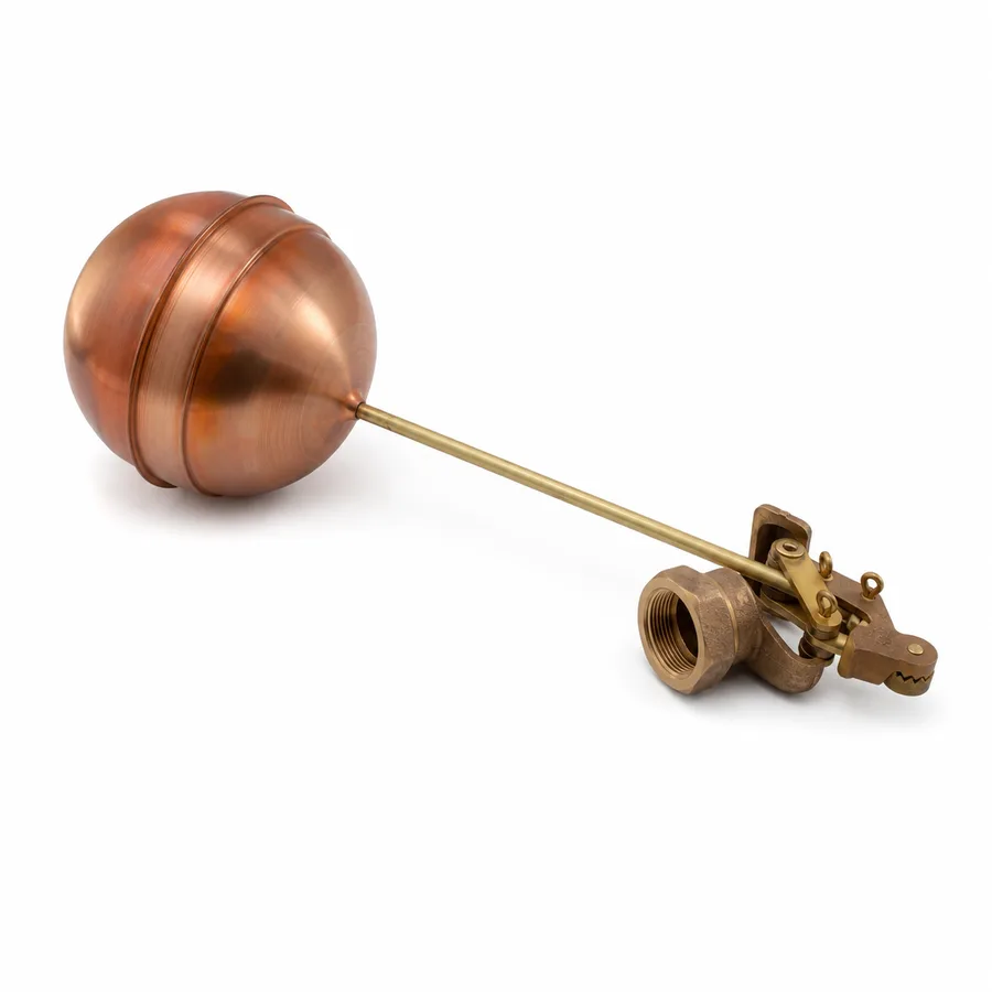
This sheet covers the metal-body float valves in the TECTUL catalog —bronze, brass and stainless steel, from 1/2″ to 3″— plus the two kit spare parts: the copper ball and the brass rod. They are tank level control valves that close through a lever mechanism: the float rises with the water, the arm pushes the plug against the seat and filling stops. The question no commercial listing answers is how much line pressure that mechanism can overcome, and why the answer depends on size. Here the manufacturer's table is published —125 psi at 1/2″-3/4″, 150 psi at 1″-1½″ with a copper ball and no published figure at 2″-3″— together with the moment balance that explains it: closing force is set by the float and the arm, while the force to overcome grows with the seat area, that is, with the square of the diameter.
Important: Before using these data in engineering, design or installation decisions on systems exposed to mechanical, pressure, rupture, fatigue, impact or water-hammer risk, it is essential to read the technical notice and limitation of liability at the end of this sheet.
SKU VT-59212 (Helman bronze float valve, 1/2″-3″, 7 sizes, complete kit with copper ball and brass rod) · metal block of 9 references: 7 valves from 1/2″ to 3″ (brass body-only version up to the complete Helbert bronze kit; stainless steel confirmed on quotation) and 2 kit spare parts (copper ball and brass rod)
1. Technical specifications: 9 metal-body references and spare parts
The float valve controls a tank's level through a purely mechanical arrangement: a float that rises with the water drives an arm, and the arm pushes a plug against the seat until filling stops. It needs no power, signal or external control. This family has no single international rating standard: the figure that governs selection is the closing pressure —how much line pressure the mechanism can overcome— and only one manufacturer in the block publishes it, and only for part of the size range. Where no figure is published, this sheet states «confirmed on quotation» instead of estimating it.
| Type | Lever-and-float level control valve, direct mechanical actuation |
| Bodies in the metal block | Cast bronze, brass and stainless steel |
| Bronze designation | Not published per reference by the manufacturer; the usual designation for cast bronze in threaded valves is ASTM B62 — confirmed on quotation |
| Rod or arm | Brass, in catalog lengths (27, 33 and 50 cm) |
| Float | Copper ball (standard kit) or plastic ball, depending on the reference |
| Plug seal | Elastomer (NBR or EPDM depending on the fluid) — not declared per reference by the manufacturer, confirmed on quotation |
| Ends | NPT thread (ASME B1.20.1) |
| Size range | 1/2″ to 3″ (DN 15 to DN 80) |
| Applicable rating figure | Manufacturer-declared closing pressure per size, not a class or a WOG/CWP system |
| Mounting position | Horizontal, with the arm free throughout its full up and down travel |
1.1 Manufacturer-published closing pressure (bronze, copper ball)
| Nominal size | Closing pressure (psi) | Closing pressure (bar) | Note |
|---|---|---|---|
| 1/2″ (DN 15) | 125 psi | 8.6 bar | Small seat; the standard kit overcomes it with margin |
| 3/4″ (DN 20) | 125 psi | 8.6 bar | Same kit as 1/2″, larger seat area |
| 1″ (DN 25) | 150 psi | 10.3 bar | The manufacturer scales up float and arm with the size |
| 1-1/4″ (DN 32) | 150 psi | 10.3 bar | — |
| 1-1/2″ (DN 40) | 150 psi | 10.3 bar | Last size with a published figure |
| 2″ (DN 50) | No published figure | Confirmed on quotation | |
| 2-1/2″ (DN 65) | No published figure | Confirmed on quotation | |
| 3″ (DN 80) | No published figure | Confirmed on quotation | |
IMPORTANT
This data sheet is a reference guide to the properties of this product type. The measurements, dimensions and physical or geometric characteristics of the product actually supplied may vary by manufacturer and lot, and may even fall outside the cited standards. If any of these figures is critical to your design or build, it is essential to verify it with one of our advisors against the physical product, so you can be fully certain of what you are buying. · Original data sheet: tectul.com/en/conduccion-de-fluidos/valvulas/ficha-tecnica-valvula-flotador-bronce.html
Catalog data from the manufacturer Helbert (a brand distributed by TECTUL) for the bronze float valve line assembled with a copper ball. Section 2 explains why the manufacturer stops publishing the value from 2″ upward. These figures do not apply to the body-only references (without a standardized rod and ball) nor to those assembled with a plastic ball: in those cases the actual closing pressure depends on the exact kit the valve is assembled with.
1.2 Metal-body references in the TECTUL catalog
| Reference | Material | Float and kit | Published sizes | Closing pressure |
|---|---|---|---|---|
| Helman bronze float valve | Bronze, brass rod | Copper ball — complete kit | 1/2″ · 3/4″ · 1″ · 1-1/4″ · 1-1/2″ · 2″ · 3″ (7) | 125 psi (1/2″-3/4″) · 150 psi (1″-1-1/2″) · 2″-3″ confirmed on quotation |
| Helbert bronze float valve | Bronze, brass rod | Copper ball — complete kit | 1/2″ · 3/4″ · 1″ · 1-1/4″ · 1-1/2″ · 2″ · 2-1/2″ · 3″ (8) | 125 psi (1/2″-3/4″) · 150 psi (1″-1-1/2″) · 2″-3″ confirmed on quotation |
| Light bronze float valve | Bronze | Light kit — confirmed on quotation | 1/2″ · 3/4″ · 1″ (3) | Confirmed on quotation |
| Bronze float valve with plastic ball | Bronze, brass rod | Plastic ball — complete kit | No active variants in catalog | Confirmed on quotation |
| Helbert brass float valve | Brass, brass rod | Copper ball — complete kit | 1/2″ · 3/4″ (2) | Confirmed on quotation |
| Helbert brass float valve, body only | Brass | No kit — body only | 1/2″ · 3/4″ (2) | Depends on the kit it is assembled with — confirmed on quotation |
| Stainless steel float valve | Stainless steel | Confirmed on quotation | No active variant record in catalog | Confirmed on quotation |
| Copper ball for float valve (spare) | Copper | Replacement float | 1/2″ · 1″ · 2″ · 3″ (4) | Not applicable |
| Helbert brass rod for float valve (spare) | Brass | Replacement arm | 27 cm · 33 cm · 50 cm (4 catalog records, two of 50 cm) | Not applicable |
IMPORTANT
This data sheet is a reference guide to the properties of this product type. The measurements, dimensions and physical or geometric characteristics of the product actually supplied may vary by manufacturer and lot, and may even fall outside the cited standards. If any of these figures is critical to your design or build, it is essential to verify it with one of our advisors against the physical product, so you can be fully certain of what you are buying. · Original data sheet: tectul.com/en/conduccion-de-fluidos/valvulas/ficha-tecnica-valvula-flotador-bronce.html
The correspondence between the published size of the spare copper ball and the size of the valve that uses it is confirmed on quotation; likewise the difference between the two 50 cm rod records. Plastic-body float valves (PVC and PA66 nylon) are not in this sheet: they are in FT-TC-VAL-FLOTADORA-PVC-001.
⚠ Important: this technical data sheet is a reference guide to the product's properties; it is not a quality certificate for the product you are buying. Heats vary from one another and may differ from the values stated here, or even depart from the standards. If your application requires compliance with a standard, always check the quality certificate (mill certificate) of the lot you are buying. If in doubt, ask one of our technical advisors →
2. Why closing pressure depends on size: the moment balance
2.1 A lever against an area
In a lever-type float valve there are two opposing forces, and they grow in different ways.
The closing force comes from the float: while the ball floats, it generates a buoyant thrust which, minus its own weight, is transmitted through the arm to the plug. By moment balance, what reaches the plug is that thrust multiplied by the lever arm ratio (pivot-to-float distance divided by pivot-to-plug distance). It is a value fixed by the kit: it depends on the ball's volume and weight and on the rod length, not on the valve size.
The force to overcome is the line pressure multiplied by the seat area. And the area grows with the square of the diameter: going from 1/2″ to 1″ does not double the force to overcome, it quadruples it at equal pressure.
Direct consequence: with the same float and arm, the maximum pressure the valve can close against falls as the seat diameter grows. If the manufacturer wants to hold the same rating at a larger size, it must enlarge the float or lengthen the arm — it cannot simply scale the body.
2.2 How to read the manufacturer's table in light of that physics
The table in section 1.1 shows exactly that managed behavior: the manufacturer publishes 125 psi at 1/2″ and 3/4″, rises to 150 psi at 1″, 1-1/4″ and 1-1/2″ —because at those sizes it scales up the float and arm kit, and the gain in closing force exceeds the gain in seat area— and stops publishing a figure from 2″ upward. That silence is not an editorial oversight: it is the point at which the seat becomes too large for the standard float and the rating would depend on a special kit, different for each installation. On a 3″ valve, the seat area is about 36 times that of a 1/2″.
What to do when the required size falls in the no-data zone: confirm with the technical team the actual line pressure at the installation point and the exact kit supplied. If the line runs at high pressure and the size is large, the direct-lever float valve stops being the right mechanism and a level control valve with pilot float applies (hydraulic actuation, another catalog family) or the internal piston mechanism of the automatic plastic line (FT-TC-VAL-FLOTADORA-PVC-001).
2.3 Confirmation from the other direction
The same physics is verified in reverse in the plastic line documented in FT-TC-VAL-FLOTADORA-PVC-001: there the manufacturer raises the rating from 100 to 150 psi by changing the float size, without touching the seat or the rod. It enlarges the float —that is, it increases the closing-force term— and recovers exactly what the diameter takes away. These are two independent manufacturer data series behaving as the moment balance predicts.
No datum in this sheet comes from testing by TECTUL. The relationship between closing pressure and size is a standard consequence of solid mechanics (moment balance and force over an area), illustrated here with the data series published by the manufacturer Helbert. The actual closing pressure of a specific unit depends on the kit it is assembled with, the seal condition and the manufacturing lot.
3. Complete or body-only, copper or plastic ball, and when stainless applies
- Potable water with a material requirement, where the specification demands an inert surface with no metal contribution to the water.
- Food and beverage industry, for cleaning and product-contact requirements.
- Chemicals and aggressive water, where brass suffers dezincification and bronze suffers chloride pitting.
The catalog's stainless reference covers that case, but it has no active variant record: size and steel grade (304 or 316) are confirmed on quotation. The difference between 304 and 316 is not cosmetic: in the presence of chlorides, 316, with molybdenum, is the one that applies.
3.4 The kit spare parts
The catalog publishes the mechanism's two consumables separately. The copper ball (sizes 1/2″, 1″, 2″ and 3″) is replaced when it is punctured or fills with water. The brass rod (lengths 27, 33 and 50 cm) is replaced when it bends, and it is the part that defines the lever arm ratio: swapping it for one of a different length changes the valve's actual closing pressure, even though the body is the same. It is not a spare part interchangeable at the installer's discretion.
4. Horizontal mounting, level adjustment and maintenance
4.1 Mounting
The lever float valve is installed horizontally, with the threaded body passing through the tank wall above the maximum level and the arm toward the inside. Three conditions decide whether it works:
- Arm free throughout its travel. The ball must be able to rise and fall without touching the tank wall, other piping, the ladder or the valve body itself. A single point of contact is enough to leave the closure incomplete and make the valve drip permanently.
- Discharge above the maximum level. The valve outlet must sit above the water level, not submerged: if it is submerged and the line loses pressure, the tank can siphon back into the line. Where the specification requires it, a backflow device or a vacuum breaker in the line also applies.
- Thread sealed with judgment. NPT thread (ASME B1.20.1) with PTFE tape or a compatible sealant; wrench on the body, never on the arm, which is the part defining the mechanism's geometry.
4.2 Adjusting the closing level
The level at which the valve shuts off is adjusted by changing the arm geometry: raising or lowering the ball's position on the rod, or slightly bending the rod on references that allow it. Two warnings that do not appear on the commercial listing:
- Bending the rod also changes the lever arm ratio, and therefore the effective closing pressure (section 2). An aggressive level adjustment can leave the valve without the force to close against line pressure.
- A very small level differential makes the valve open and close continuously with every ripple of the surface. That cycling wears the seal and the pivot faster than the flow does.
4.3 Maintenance and diagnosis
| Symptom | Probable cause | What to check |
|---|---|---|
| Continuous leak with the tank full | Plug seal worn or with embedded sediment | Dismantle and inspect the elastomeric seal; it is the mechanism's normal wear point. It is not a lack of closing pressure |
| The valve does not close fully and the arm stays at mid height | Punctured ball full of water, or arm rubbing against an obstruction | Remove the ball and check for water inside; check the arm's free travel |
| It closes but reopens on its own at full line pressure | Line pressure above the assembly's closing pressure | Compare the actual pressure at the point against the table in section 1.1; check the installed kit. It may require a larger-float kit or a change of mechanism |
| Play or knocking in the arm | Worn pivot | It is the mechanism's second wear point, after the seal |
| Continuous open-close cycling | Level differential too narrow or agitated water surface | Readjust the closing level; if filling agitates the surface, redirect the discharge or move the float away |
5. Frequently asked questions
How much pressure does a bronze float valve withstand?
The figure that matters is not how much pressure the body withstands but how much pressure it can close against. The manufacturer publishes 125 psi (8.6 bar) at 1/2″ and 3/4″ and 150 psi (10.3 bar) at 1″, 1-1/4″ and 1-1/2″, assembled with a copper ball. From 2″ to 3″ it publishes no figure and it is confirmed on quotation. If the line pressure at the installation point exceeds that value, the valve closes and reopens on its own.
Why does closing pressure drop as the size increases?
Because closing force is set by the float and the arm —constant for a given kit— while the force to overcome is pressure times the seat area, and the area grows with the square of the diameter. A 3″ valve has a seat about 36 times the area of a 1/2″ one. To hold the rating at larger sizes the manufacturer must enlarge the float or lengthen the arm; when that stops being practical, it stops publishing the value.
What is the difference between the «complete» and «body-only» float valve?
The complete one includes the rod and ball kit already assembled; the body-only one is just the valve body, for those who already have the kit or will assemble a different combination. The practical consequence is that the published closing pressure applies only to the complete version with its kit: the actual closing pressure of a body-only unit depends on the float and arm it is assembled with and is confirmed on quotation.
Copper ball or plastic ball?
The copper ball is the one in the kit with a published closing pressure: rigid, stable against sun and temperature, and repairable by soldering if punctured. The plastic one is cheaper and lighter and does not corrode, but it has no published closing pressure and degrades sooner under ultraviolet radiation and impact. If the criterion is a declared closing pressure, the copper ball is what backs it.
When does a stainless float valve apply instead of bronze or brass?
In potable water with a material requirement, in the food and beverage industry, and in chemicals or aggressive water where brass suffers dezincification and bronze suffers chloride pitting. The catalog's stainless reference has no active variants: size and grade (304 or 316) are confirmed on quotation. With chlorides present, the applicable grade is 316.
The valve drips with the tank full — is that a lack of closing pressure?
No. A continuous leak with the tank full and the arm up points to a worn plug seal or one with embedded sediment, or to an arm rubbing against an obstruction and not reaching the stop. A lack of closing pressure gives a different symptom: the valve closes and reopens on its own against the line at full pressure.
Does it work for a domestic toilet tank?
It is not the same part. The float valves in this sheet are for storage tanks, cisterns and industrial or agricultural applications, with 1/2″ to 3″ connections and metal bodies. Domestic toilet fill valves use a miniature internal float mechanism with a different connection and a different body: they share the physical principle, not the catalog or the application, and they are not interchangeable.
6. Application notes
Feasibility
For tank level control with a manufacturer-backed closing pressure, the bronze float valve with a copper-ball kit (Helman or Helbert) covers the 1/2″ to 1-1/2″ range: 125 psi at 1/2″-3/4″ and 150 psi at 1″-1-1/2″. At 2″, 2-1/2″ and 3″ the manufacturer publishes no closing pressure and the assembly is confirmed with the technical team against the actual line pressure. The brass versions cover 1/2″ and 3/4″, and the body-only version serves only when the customer already has the kit, because its closing pressure depends on what it is assembled with. For potable water with a material requirement, food and beverage or chemicals with chlorides, no copper alloy applies: a stainless body is required, with grade (304 or 316) to be confirmed. If the size is large and line pressure high, the direct lever stops being the right mechanism and a level control valve with pilot float applies, or the internal piston mechanism of the plastic line (FT-TC-VAL-FLOTADORA-PVC-001).
Installation
Install the valve horizontally, through the tank wall above the maximum level, with the discharge above the water level and never submerged. Keep the arm free of obstructions —tank wall, piping, ladder, the body itself— throughout its full up and down travel: a single point of contact leaves the closure incomplete and the valve dripping. Seal the NPT thread (ASME B1.20.1) with PTFE tape or a compatible sealant and wrench on the body, never on the arm. Adjust the closing level by moving the ball on the rod; bear in mind that bending the rod also changes the lever arm ratio and therefore the effective closing pressure. Avoid a level differential so narrow that the valve cycles with every ripple of the surface: that cycling wears the seal and pivot faster than the flow itself.
Design
Do not size the float valve by connection diameter alone: check the actual line pressure at the installation point against the published closing pressure for that size and kit (section 1.1). If the required size falls in the no-published-data zone (2″ to 3″ in bronze), or if the reference is a body-only or plastic-ball version, confirm the assembly with the technical team before specifying: closing pressure is a property of the assembly, not of the body. Note that the rod length is a design parameter, not an interchangeable accessory: changing it alters the lever arm ratio and with it the closing pressure. If the installation requires backflow protection toward the line, provide the corresponding backflow device or vacuum breaker, which is not part of this valve. None of these values replaces the project's hydraulic design under the code governing the installation.
7. Technical notice and limitation of liability
The closing pressures in section 1.1 are data published by the manufacturer Helbert (a brand distributed by TECTUL) for its bronze float valve line assembled with a copper ball. The sizes and materials in the rest of the sheet are catalog values declared by TECTUL from its own variant records (Jul-Aug 2026 list). This family has no single international rating standard: each manufacturer sets its own. These data guide selection; they are not a certificate of conformity for any given unit nor independent testing by TECTUL.
Closing pressure is a property of the assembly, not of the valve body: it depends on the float's volume and weight, the arm length, the seal hardness and the manufacturing lot. The published values apply to the complete version with its copper-ball kit at the sizes indicated. For the body-only references, the plastic-ball ones, the light version, the stainless one and the 2″ to 3″ sizes, the manufacturer publishes no value and this sheet states «confirmed on quotation» instead of inventing one.
The relationship between closing pressure and size set out in section 2 is a standard consequence of solid mechanics (moment balance and force over an area), illustrated with the manufacturer's data series; it is not a TECTUL measurement nor a selection formula. These values must not be used as the sole criterion in critical or safety applications, nor wherever level-control failure may compromise people, property or the environment —tank overflow, contamination by backflow into the line, loss of supply to a process—: in such cases the design belongs to the project's responsible engineer. Before deciding with these data, consult our technical team.
Sources
- Catálogo del fabricante Helbert y Cía (marca distribuida por TECTUL) — presión de cierre por diámetro de las válvulas flotadoras en bronce armadas con bola de cobre: 125 psi en 1/2″ y 3/4″, 150 psi en 1″, 1-1/4″ y 1-1/2″, sin dato publicado de 2″ a 3″
- Catálogo y fichas del fabricante Helman (marca distribuida por TECTUL) — configuración del kit completo de la flotadora en bronce (cuerpo, varilla de latón y bola de cobre) y diámetros disponibles de 1/2″ a 3″
- ASME B1.20.1 — Pipe Threads, General Purpose (Inch): rosca NPT de los extremos roscados del bloque metálico; la tabla canónica de hilos por pulgada, L2, L4 y profundidad de filete está publicada en FT-TC-ACC-NIP-001 y no se repite aquí
- ASTM B62 — Standard Specification for Composition Bronze or Ounce Metal Castings: designación habitual del bronce fundido en válvulas roscadas; los fabricantes de estas referencias no la declaran por producto, por lo que aquí se cita como referencia y se confirma al cotizar
- ASTM A276 / ASTM A351 — grados de acero inoxidable austenítico 304 y 316 para componentes de válvula: base de la distinción entre 304 y 316 en presencia de cloruros, aplicable a la referencia inoxidable cuyo grado se confirma al cotizar
- Principio de balance de momentos y fuerza hidrostática sobre un área (mecánica de sólidos y estática de fluidos, literatura de ingeniería estándar) — base física de la relación entre presión de cierre, tamaño del flotador, longitud del brazo y área del asiento expuesta en la sección 2
- Catálogo y plano de fabricante LD-85SA — LD Pipe Fittings & Valves, válvula flotadora PVC modelo LD-856A: serie de datos independiente citada en la sección 2.3 como confirmación inversa de la misma física (100 psi con boya de 6″ y 150 psi con boya de 8″); los datos completos de esa línea están en FT-TC-VAL-FLOTADORA-PVC-001 y no se repiten aquí
- data/etapas/etapa-1-conduccion-de-fluidos/curaduria.json y data/scraped/products/*.json del catálogo TECTUL — longitudes de varilla y descripciones comerciales de las 9 referencias metálicas de esta ficha (registro interno, jul-ago 2026)
This data sheet is the property of TECTUL, part of the Industrias IMR group. Reproduction without attribution is prohibited. Original document and updates: tectul.com/en/conduccion-de-fluidos/valvulas/ficha-tecnica-valvula-flotador-bronce.html.