 TECTULby IMR
Carbon steel globe valve — cast flanged API 623 class 150 and forged compact API 602 class 800
TECTUL · Dispatch across Colombia · Exports to Central & South America
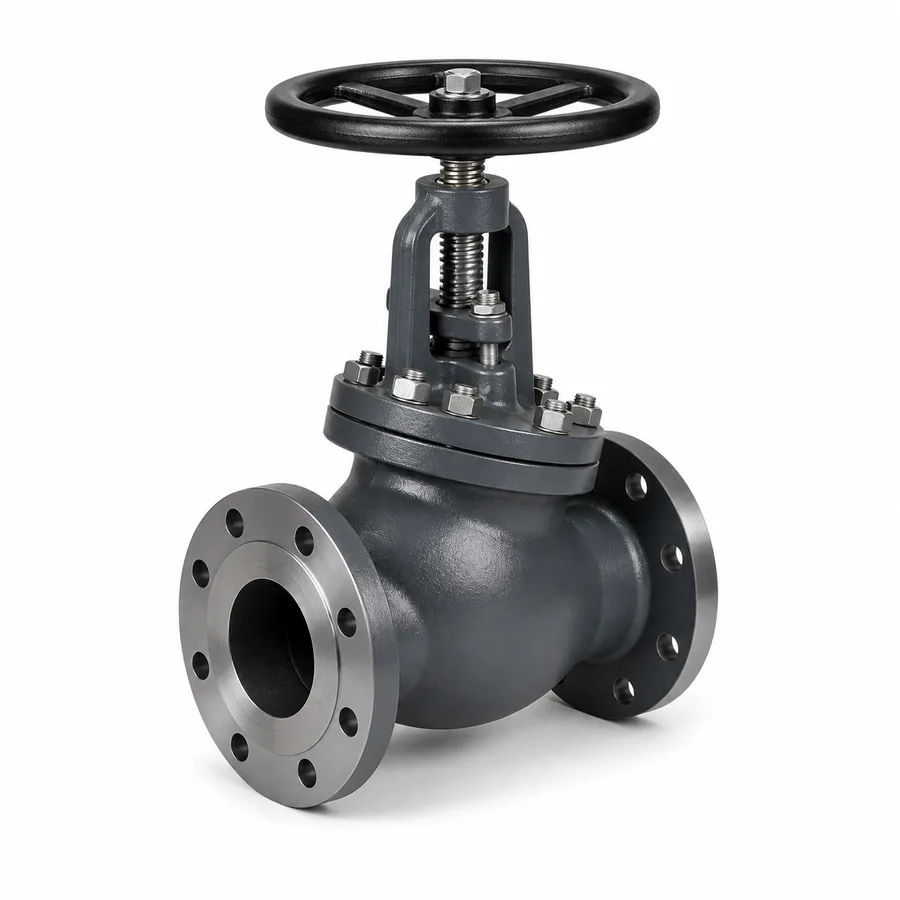
TECTUL's carbon steel globe valve in two constructions: cast flanged in A216 WCB per API 623 (conical or plug seat, bolted bonnet, class 150 flanged ends per ASME B16.5), and forged compact in A105 per API 602 (threaded NPT or socket-weld ends, 1/2″ to 2″, Class 800 — not "800 psi": its real cold ceiling is 1,973 psig, 136 bar, at 38 °C). Unlike the gate valve in this same family, the globe valve does throttle flow: its conical seat and S-shaped flow path allow stable intermediate positions, in exchange for a much higher head loss even fully open — the datum no Spanish-language commercial sheet publishes with its coefficient.
Important: Before using these data in engineering, design or installation decisions on systems exposed to mechanical, pressure, rupture, fatigue, impact or water-hammer risk, it is essential to read the technical notice and limitation of liability at the end of this sheet.
SKU VT-valvula-globo-acero-al-carbon-bridada · 2 constructions: cast flanged class 150 (2″–12″) and forged compact class 800 (1/2″–2″, catalog alias)
1. Technical specifications
Two constructions, one material
| Construction | Cast flanged: body and bonnet in A216 WCB casting, plug or conical disc over a renewable seat, bolted bonnet, outside-screw-and-yoke (OS&Y) stem in most manufacturers. Class 150 flanged ends per ASME B16.5. |
| Forged compact: A105 forged body, plug disc, threaded or welded bonnet depending on reference. NPT threaded ends (ASME B1.20.1) or socket-weld (ASME B16.11). | |
| Sizes | Cast flanged: 2″ to 12″ (DN 50–DN 300). Forged compact: 1/2″ to 2″ (DN 15–DN 50), listed in the catalog as Válvula Globo Acero Al Carbón 800 Psi. |
| Product standard | Cast: API 623 (Steel Globe Valves — Flanged and Butt-welding Ends, Bolted Bonnets). Forged: API 602 (Compact Steel Gate, Globe and Check Valves, DN 100 and smaller). |
| Pressure-temperature rating | ASME B16.34, material group 1.1 in both cases (A216 WCB and A105): class 150 for the flanged one, Class 800 for the forged one — the same name correction as the gate valve in this family: the forged one is NOT "800 psi", it is Class 800 (1,973 psig at 38 °C). |
| Face-to-face dimensions | Cast flanged: ASME B16.10, globe pattern (longer than the gate pattern at the same size, due to the S-shaped internal path). Forged compact: its own API 602 pattern, not under B16.10. |
| Ends | Flanged: class 150 per ASME B16.5. Forged: NPT thread or socket-weld. |
| Tests | Seat and shell per API 598. |
IMPORTANT
This data sheet is a reference guide to the properties of this product type. The measurements, dimensions and physical or geometric characteristics of the product actually supplied may vary by manufacturer and lot, and may even fall outside the cited standards. If any of these figures is critical to your design or build, it is essential to verify it with one of our advisors against the physical product, so you can be fully certain of what you are buying. · Original data sheet: tectul.com/en/conduccion-de-fluidos/valvulas/ficha-tecnica-valvula-globo-acero-al-carbon-bridada.html
Pressure-temperature table — class 150 cast (A216 WCB, B16.34 group 1.1)
| Temperature | Allowable pressure |
|---|---|
| −29 to 38 °C (−20 to 100 °F) | 285 psig (19.6 bar) |
| 93 °C (200 °F) | 260 psig (17.9 bar) |
| 149 °C (300 °F) | 230 psig (15.9 bar) |
| 204 °C (400 °F) | 200 psig (13.8 bar) |
| 260 °C (500 °F) | 170 psig (11.7 bar) |
| 316 °C (600 °F) | 140 psig (9.7 bar) |
IMPORTANT
This data sheet is a reference guide to the properties of this product type. The measurements, dimensions and physical or geometric characteristics of the product actually supplied may vary by manufacturer and lot, and may even fall outside the cited standards. If any of these figures is critical to your design or build, it is essential to verify it with one of our advisors against the physical product, so you can be fully certain of what you are buying. · Original data sheet: tectul.com/en/conduccion-de-fluidos/valvulas/ficha-tecnica-valvula-globo-acero-al-carbon-bridada.html
Pressure-temperature table — Class 800 forged (A105, B16.34 group 1.1, interpolated 1/3 class 600 + 2/3 class 900)
| Temperature | Allowable pressure |
|---|---|
| −29 to 38 °C (−20 to 100 °F) | 1,973 psig (136 bar) |
| 93 °C (200 °F) | 1,800 psig (124 bar) |
| 149 °C (300 °F) | 1,752 psig (121 bar) |
| 204 °C (400 °F) | 1,690 psig (116 bar) |
| 260 °C (500 °F) | 1,597 psig (110 bar) |
IMPORTANT
This data sheet is a reference guide to the properties of this product type. The measurements, dimensions and physical or geometric characteristics of the product actually supplied may vary by manufacturer and lot, and may even fall outside the cited standards. If any of these figures is critical to your design or build, it is essential to verify it with one of our advisors against the physical product, so you can be fully certain of what you are buying. · Original data sheet: tectul.com/en/conduccion-de-fluidos/valvulas/ficha-tecnica-valvula-globo-acero-al-carbon-bridada.html
Class 150: Table 2-1.1 of ASME B16.34, material group 1.1. Class 800: 38 °C anchor value (1,973 psig) verified against API 602 line manufacturers; higher-temperature points result from the same linear interpolation applied at each step (method detail in the sister gate valve sheet, FT-TC-VAL-COMPUERTA-AC-001) and should be checked against the manufacturer's full table before a critical design.
Face-to-face dimensions — cast flanged, class 150 (ASME B16.10, globe pattern)
| Size | Face-to-face (RF) |
|---|---|
| 2″ | 203 mm |
| 3″ | 241 mm |
| 4″ | 292 mm |
| 6″ | 406 mm |
| 8″ | 495 mm |
| 10″ | 622 mm |
| 12″ | 698 mm |
IMPORTANT
This data sheet is a reference guide to the properties of this product type. The measurements, dimensions and physical or geometric characteristics of the product actually supplied may vary by manufacturer and lot, and may even fall outside the cited standards. If any of these figures is critical to your design or build, it is essential to verify it with one of our advisors against the physical product, so you can be fully certain of what you are buying. · Original data sheet: tectul.com/en/conduccion-de-fluidos/valvulas/ficha-tecnica-valvula-globo-acero-al-carbon-bridada.html
Note that at the same nominal size the globe valve is longer than the gate valve (for example 4″: 292 mm globe versus 229 mm gate): the globe's internal path bends the flow in an S shape instead of leaving it straight, and that geometry — not a design whim — is also the origin of its higher head loss (section 2). The forged compact Class 800 valve has no F2F table in B16.10; its dimension is set by API 602 and the manufacturer — confirmed on quotation.
⚠ Important: this technical data sheet is a reference guide to the product's properties; it is not a quality certificate for the product you are buying. Heats vary from one another and may differ from the values stated here, or even depart from the standards. If your application requires compliance with a standard, always check the quality certificate (mill certificate) of the lot you are buying. If in doubt, ask one of our technical advisors →
2. Why the globe valve throttles flow and the gate valve does not
Seat geometry decides the use
A gate valve closes with a flat wedge that descends perpendicular to the flow: in an intermediate position, the wedge's lower edge is exposed to a concentrated, high-velocity jet that erodes the metal within a few hours of throttled operation — that is why a gate valve is always specified for full shut-off, open or closed, never halfway. A globe valve, by contrast, closes with a conical or plug disc that descends onto a circular seat concentric with the stem axis: the flow area narrows progressively and in a controlled way as the disc approaches the seat, and the conical profile spreads the pressure drop over a larger fluid volume instead of concentrating it on an edge. That is the underlying difference, not a matter of manufacturing quality: the globe valve is designed to work in an intermediate position; the gate valve is not.
Head-loss coefficient: the figure missing from the Spanish-language SERP
The trade-off for that throttling capability is a much higher permanent head loss, even with the valve fully open, because the flow must turn twice in an S shape to cross the globe's seat (it enters, rises or descends toward the seat, and turns again toward the outlet), while in an open gate valve the flow passes straight through a bore nearly the full diameter of the pipe.
| Valve, fully open | L/D (equivalent length in pipe diameters) |
|---|---|
| Ball valve (full port) | 3 |
| Gate valve | 8 |
| Butterfly valve (2″–8″) | 45 |
| Swing check valve | 100 |
| Globe valve, conventional pattern | 340 |
Equivalent length values (K = n × fT, with fT the fully-turbulent friction factor of the pipe size) from the Crane Technical Paper No. 410 method (Flow of Fluids Through Valves, Fittings, and Pipe), the industry reference for calculating fitting head loss. A fully open globe valve loses roughly 43 times more head than a fully open gate valve of the same size (340 versus 8) — a figure that decides pump sizing and that no Spanish-language commercial sheet publishes alongside the pressure rating.
Flow direction under the disc
Most globe valves in this family are designed so the fluid enters under the disc and pushes upward when opening ("flow-under-seat"), not the reverse. That orientation serves two purposes: line pressure helps lift the disc when opening instead of opposing the stem, and on closing, upstream pressure pushes the disc against its seat in the same direction the stem seats it, reinforcing the seal. Installing the globe valve backwards — with flow pushing the disc from above — does not prevent it from closing but reverses both advantages: the stem must overcome line pressure to open, and the seal on closing depends solely on stem force. The arrow cast on the body indicates the correct direction and must be followed.
Seat wear under severe throttling
Even with its more favorable geometry for regulation, the globe valve is not immune to wear when operated near full closure with a high differential pressure: at very small openings, local velocity through the narrow ring between disc and seat rises sharply, bringing the risk of cavitation (collapse of vapor bubbles that erodes the seat metal) and disc vibration. Typical symptoms of a globe valve worked under severe, prolonged throttling are a sharp noise from the valve, visible erosion of the seat edge and progressive loss of shut-off tightness. When the service requires fine, continuous throttling — not occasional — with high differential pressure, a dedicated control valve with a seat profile designed for that specific pressure drop is the correct choice, not an isolation globe valve operated as if it were a control valve.
3. Materials, graphite packing and seat trim
Materials by component
| Body and bonnet (cast) | A216 WCB, ASME B16.34 material group 1.1 |
| Body (forged) | A105, same material group 1.1 (shares the rating table with WCB) |
| Disc and seat | Hardened sealing surfaces by trim (see the API trim table in the sister gate valve sheet, FT-TC-VAL-COMPUERTA-AC-001, section 3): 13Cr (Trim 1), Stellite (Trim 5/8) for frequent throttling service or particle-laden fluid, or 316 (Trim 10) for moderate chlorides |
| Stem | 13Cr, outside-screw-and-yoke (OS&Y) in most cast flanged manufacturers; inside stem in several forged compact references |
| Stem box packing | Flexible graphite, asbestos-free |
| Bonnet gasket | Spiral-wound graphite or equivalent for steam and high-temperature service |
Why seat trim matters more here than on the gate valve
The globe valve is chosen precisely because it will work near closure frequently — that is its function. That repeated closeness between disc and seat wears the sealing surfaces faster than on a gate valve that only operates fully open or fully closed. That is why, when the service includes routine throttling (not just shut-off), specifying a Stellite-hardened trim instead of the base 13Cr trim is worthwhile: the surface better resists repeated rubbing and particles carried by the fluid. The exact trim per reference is confirmed on quotation.
Graphite packing: the same reason as the gate valve
Like the gate valve in this family, the steel globe valve works in steam and temperature services above the practical PTFE limit (≈180 °C), so the stem seal is flexible graphite packing compressed by the gland, not an elastomer or PTFE. It requires periodic re-tightening as the graphite settles and a pitting-free stem surface so as not to open a leak path that tightening no longer closes.
4. Frequently asked questions
Can I use this globe valve to throttle flow?
Yes — that is its function. The globe valve's conical seat and S-shaped path allow stable intermediate positions, unlike the gate valve in this same family, which must only be operated fully open or fully closed. The trade-off is a much higher permanent head loss (L/D 340 versus 8 for the gate valve, section 2), which must be accounted for in pump sizing.
Does the "800 psi" carbon steel globe valve really only take 800 psi?
No. It is ASME B16.34/API 602 Class 800, whose real cold ceiling is 1,973 psig (136 bar) at 38 °C. The commercial name is a legacy catalog simplification; this sheet uses the verified figure (section 1).
Why does a globe valve lose more pressure than a gate valve?
Because the flow must turn twice in an S shape to cross the globe's seat, while in an open gate valve it passes straight through a bore nearly the full diameter of the pipe. Using the Crane TP-410 method, the equivalent length of a fully open globe valve is L/D 340, versus L/D 8 for a gate valve: roughly 43 times more head loss at the same size.
Does installation direction matter on a globe valve?
Yes. Most are designed so flow enters under the disc and pushes it upward when opening: line pressure then helps opening and reinforces the seal on closing. Installed backwards, the stem must overcome line pressure to open and the seal on closing depends solely on stem force. The arrow cast on the body indicates the correct direction.
Can this globe valve be used as a precision control valve?
Not for fine, continuous throttling with high differential pressure: at very small openings there is a risk of cavitation and disc vibration, which erodes the seat quickly. For that service a dedicated control valve, with a seat profile designed for the specific pressure drop, is the correct choice.
What is the difference between the flanged and forged constructions in this sheet?
The flanged one (API 623, class 150, 285 psig at 38 °C) covers 2″ to 12″ with flanged ends. The forged compact one (API 602, Class 800, 1,973 psig at 38 °C) covers small sizes, 1/2″ to 2″, with threaded or socket-weld ends — more common in instrumentation and high-pressure sampling lines than in main plant piping.
5. Application notes
Feasibility
The API 623 class 150 cast flanged valve (285 psig at 38 °C) covers steam, water, oil and compatible hydrocarbon regulation from 2″ to 12″, when the service requires occasional or moderate continuous throttling, not just shut-off. The API 602 forged compact Class 800 valve (1,973 psig at 38 °C, not 800 psi) covers the same kind of regulation in the small sizes of instrumentation and high-pressure drain lines, 1/2″ to 2″. It is not the choice for free flow with minimal head loss — that is the gate valve in this same family — nor for fine, continuous throttling with high differential pressure, where a dedicated control valve is the correct choice. For critical or safety applications, consult our technical team before specifying.
Installation
Follow the flow-direction arrow cast on the body: the usual design enters under the disc. Leave clearance above the stem yoke for its full travel. Align flanges before bolting (flanged) or use a thread sealant compatible with the fluid (forged threaded). Account for the globe valve's head loss (L/D 340) in the line's hydraulic calculation, not just that of the minor fittings. Re-tighten the graphite gland after the first hours of operation.
Design
Size the line with the globe valve's head loss already included (L/D 340 fully open, section 2), not just the static pressure: on long or small-diameter lines that difference against a gate valve may require a higher-head pump. For the forged Class 800, use 1,973 psig as the ceiling at 38 °C, not 800 psi. If the service requires fine, continuous throttling with high differential pressure, specify a dedicated control valve instead of this general-purpose globe valve. Set the seat trim by the expected throttling frequency (section 3): Stellite for frequent use, base 13Cr for occasional shut-off.
6. Technical notice and limitation of liability
The pressure-temperature ratings in this sheet combine values published directly in ASME B16.34 (class 150, material group 1.1) with Class 800 values obtained by documented linear interpolation (1/3 of Class 600 + 2/3 of Class 900 of the same group), consistent with what API 602 line manufacturers publish. Head-loss coefficients (L/D) come from the Crane Technical Paper No. 410 method, the industry's calculation reference. They are nominal reference values; they are not a certificate of conformity for any production lot nor an independent test of the TECTUL catalog reference.
The "800 psi → Class 800" name correction is an engineering clarification of our own catalog, not a certification of the actual manufacturer of each lot: trim, stem type, forged valve face-to-face dimensions and material certificate are confirmed on quotation with factory documentation.
These values must not be used as the sole criterion in critical, safety applications, or wherever valve failure may compromise people, property or the environment: in such cases the design belongs to the project's responsible engineer, under the applicable piping code (ASME B31.1 or B31.3) and with the line's real design temperature. Before deciding with these data, consult our technical team.
Sources
- API Standard 623 — Steel Globe Valves — Flanged and Butt-welding Ends, Bolted Bonnets: construcción de la globo fundida bridada
- API Standard 602 — Compact Steel Gate, Globe, and Check Valves for Sizes DN 100 (NPS 4) and Smaller: construcción forjada compacta y clases de presión
- ASME B16.34 — Valves — Flanged, Threaded, and Welding End: Tabla 2-1.1, grupo de material 1.1 (A216 WCB / A105); método de interpolación de la Clase 800 (1/3 clase 600 + 2/3 clase 900)
- ASME B16.10 — Face-to-Face and End-to-End Dimensions of Valves: patrón de globo clase 150, 2″ a 12″
- ASME B16.5 — Pipe Flanges and Flanged Fittings: bridas clase 150 de los extremos de la construcción fundida
- ASME B1.20.1 — Pipe Threads, General Purpose (Inch) / ASME B16.11 — Forged Fittings, Socket-Welding and Threaded: extremos de la construcción forjada
- API Standard 598 — Valve Inspection and Test
- Crane Co. — Flow of Fluids Through Valves, Fittings and Pipe (Technical Paper No. 410): coeficientes de longitud equivalente L/D de compuerta (8), globo convencional (340), bola paso total (3), mariposa (45) y retención de columpio (100)
- ASTM A216/A216M — Standard Specification for Steel Castings, Carbon, Suitable for Fusion Welding, for High-Temperature Service (grado WCB)
- ASTM A105/A105M — Standard Specification for Carbon Steel Forgings for Piping Applications (construcción forjada API 602)
This data sheet is the property of TECTUL, part of the Industrias IMR group. Reproduction without attribution is prohibited. Original document and updates: tectul.com/en/conduccion-de-fluidos/valvulas/ficha-tecnica-valvula-globo-acero-al-carbon-bridada.html.