 TECTULby IMR
Concentric butterfly valve in ductile iron with stainless disc — wafer, lug and grooved-end, 2″ to 12″
TECTUL · Dispatch across Colombia · Exports to Central & South America
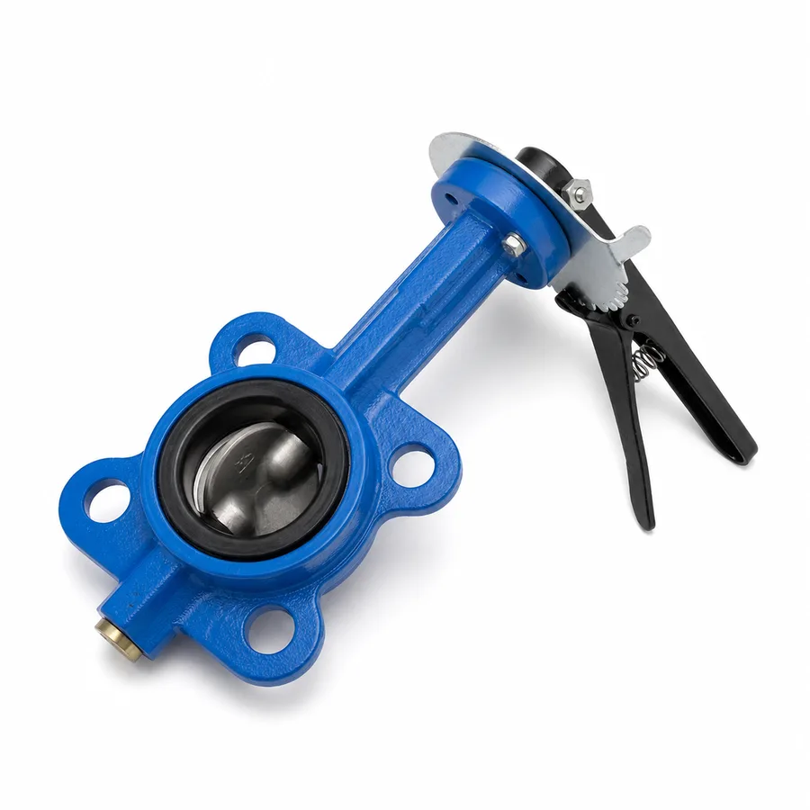
Concentric butterfly valve with an ASTM A536 ductile iron body and a stainless steel disc, offered in the TECTUL catalog in three mounting systems: wafer (sandwiched between two flanges by through studs), lug (with threaded lugs that allow each side to be bolted independently) and grooved-end geared type (grooved ends for mechanical coupling, no flanges). The seat —EPDM, NBR or PTFE depending on reference— is in practice the component that sets the service temperature ceiling, not the ductile iron body, which comfortably withstands far higher pressures and temperatures than any elastomer. This sheet publishes the stud and bolt-circle table by size for the wafer mounting against ASME B16.5 class 150 flanges, the ASME PCC-1 cross-pattern tightening sequence, the rule of opening the disc slightly before tightening so it does not strike the pipe, the ISO 5211 actuator interface table with operating torque growing by size, and the practical difference between wafer and lug for end-of-line service.
Important: Before using these data in engineering, design or installation decisions on systems exposed to mechanical, pressure, rupture, fatigue, impact or water-hammer risk, it is essential to read the technical notice and limitation of liability at the end of this sheet.
SKU VT-59219 (wafer stainless disc, ductile iron body) · family of 4 mounting references: elastomeric-seat wafer, PTFE-seat wafer, threaded-lug and grooved-end geared type
1. Technical specifications
Materials and construction
| Body | Ductile iron, typical grade 65-45-12 per ASTM A536 (yield strength ≈45 ksi, minimum elongation 12 %), with epoxy coating on most commercial references |
| Disc | 300-series austenitic stainless steel (typically equivalent to 304 or 316 depending on reference), with 1/4-turn rotation on the central shaft |
| Shaft | Stainless steel, through-shaft or two half-shafts depending on design, with support bushings and seals at the operator outlet |
| Seat | Elastomeric —EPDM or NBR depending on fluid— shaped as a liner covering the body, or PTFE on the Teflon-seat reference for chemical service or higher temperature |
| Operator | Notched lever with fixed positions on smaller sizes; gear operator with handwheel on larger sizes; ISO 5211 preparation across the whole line |
| Reference standards | API 609 (valve type and category) · MSS SP-67 (general requirements for butterfly valves) · ASTM A536 (body) · ASME B16.5 (mating flange of the wafer mounting) · ISO 5211 (actuator interface) |
The four mounting references in the TECTUL catalog
| Reference | Mounting system | Catalog sizes |
|---|---|---|
| Wafer stainless disc, ductile iron body | Wafer — sandwiched between two flanges with through studs | 2″ · 2-1/2″ · 3″ · 4″ · 6″ · 8″ |
| Wafer PTFE seat | Wafer — same mounting principle, PTFE seat | 2″ to 8″ (per reference; confirm exact size on quotation) |
| Lug stainless disc | Lug — threaded lugs bolted to each flange independently | 2″ to 8″ (per reference; confirm exact size on quotation) |
| Grooved-end geared type | Grooved ends for mechanical coupling — no flanges or studs | 2″ · 2-1/2″ · 3″ · 4″ · 6″ · 8″ · 10″ · 12″ |
IMPORTANT
This data sheet is a reference guide to the properties of this product type. The measurements, dimensions and physical or geometric characteristics of the product actually supplied may vary by manufacturer and lot, and may even fall outside the cited standards. If any of these figures is critical to your design or build, it is essential to verify it with one of our advisors against the physical product, so you can be fully certain of what you are buying. · Original data sheet: tectul.com/en/conduccion-de-fluidos/valvulas/ficha-tecnica-valvula-mariposa-disco-inoxidable-cuerpo-hierro.html
The first three references share the same sealing principle against flanges (section 3); the grooved-end one uses a different mechanical coupling system, unrelated to the flanged mounting (section 3, last block).
⚠ Important: this technical data sheet is a reference guide to the product's properties; it is not a quality certificate for the product you are buying. Heats vary from one another and may differ from the values stated here, or even depart from the standards. If your application requires compliance with a standard, always check the quality certificate (mill certificate) of the lot you are buying. If in doubt, ask one of our technical advisors →
2. Rating system: the seat governs, not the ductile iron body
ASTM A536 ductile iron is a mechanically strong material: it comfortably withstands pressures and temperatures far higher than this valve will ever see in normal service. However, no soft-seated concentric butterfly valve is specified by the strength of its body: the working pressure and temperature published by the manufacturer are set by the weakest link in the chain, which is the seat —elastomeric or PTFE—, not the iron. This is the central accuracy correction for this family: the pressure figure of a soft-seated butterfly valve is not an ASME B16.34 class (that table is for metal-seated flanged steel valves, not resilient-seated butterfly valves), but rather a manufacturer working pressure by size, referenced to the seat temperature, per the general API 609 framework (which classifies resilient-seated butterfly valves as Category A —wafer and lug, short body— versus Category B high-performance valves with metal or laminated seats). The exact value by size and reference for this line is confirmed on quotation; what this sheet fixes is the criterion for reading it correctly.
Temperature range by seat type
| Seat | Typical temperature range | Typical use |
|---|---|---|
| EPDM | −40 °C to 120 °C (−40 °F to 250 °F) | Cold and hot water, many dilute chemicals; not suitable for hydrocarbons or mineral oils |
| NBR (nitrile) | −30 °C to 100 °C (−22 °F to 212 °F) | Oils, hydrocarbons and greases; poorer ozone and weathering resistance than EPDM |
| PTFE | −20 °C to 200 °C (−4 °F to 392 °F) | Aggressive chemicals, vapors and higher temperature where the elastomer does not hold; requires higher operating torque due to its lower elasticity (section 4) |
Reference ranges from industry practice for elastomeric and PTFE valve seat compounds, consistent with the chemical and thermal compatibility charts published by sealing compound manufacturers. The real limit of each reference —including the maximum pressure at each temperature— depends on the manufacturer's exact compound and is confirmed on quotation. The ductile iron body's temperature limit never governs: the seat always governs.
Practical consequence of the rule
Specifying this valve only by size and line pressure, without fixing the seat, is incomplete: two valves identical in body and disc can have very different temperature limits depending on whether they carry EPDM, NBR or PTFE. And conversely, moving from an elastomeric seat to PTFE for chemical resistance does not increase the body's working pressure —that is set by the size and the disc design—, it only changes compatibility and the thermal range.
3. Wafer and lug mounting: studs by size, cross-pattern tightening and wafer vs. lug
Studs and bolt circle of the wafer mounting — class 150 (ASME B16.5)
| Size | Number of studs | Stud diameter | Bolt circle |
|---|---|---|---|
| 2″ | 4 | 5/8″ | 4.75″ (120.7 mm) |
| 2-1/2″ | 4 | 5/8″ | 5.50″ (139.7 mm) |
| 3″ | 4 | 5/8″ | 6.00″ (152.4 mm) |
| 4″ | 8 | 5/8″ | 7.50″ (190.5 mm) |
| 6″ | 8 | 3/4″ | 9.50″ (241.3 mm) |
| 8″ | 8 | 3/4″ | 11.75″ (298.5 mm) |
IMPORTANT
This data sheet is a reference guide to the properties of this product type. The measurements, dimensions and physical or geometric characteristics of the product actually supplied may vary by manufacturer and lot, and may even fall outside the cited standards. If any of these figures is critical to your design or build, it is essential to verify it with one of our advisors against the physical product, so you can be fully certain of what you are buying. · Original data sheet: tectul.com/en/conduccion-de-fluidos/valvulas/ficha-tecnica-valvula-mariposa-disco-inoxidable-cuerpo-hierro.html
Data for the ASME B16.5 class 150 flange, the mating part of the wafer and lug mounting (studs are through studs on wafer, crossing flange to flange; on lug they thread directly into the body's lugs, see below). The final torque per size is set by the valve manufacturer according to the seat and is confirmed on quotation.
Cross-pattern tightening sequence (ASME PCC-1)
- Fit the valve with the disc slightly open, not protruding beyond the flange faces: this way it does not catch or strike the pipe or the adjacent flange while centring, and the seat is not loaded by the disc while it is compressed.
- Align and centre the body between the two flanges, checking parallelism before fitting the studs.
- Bring the nuts to contact by hand on every stud, checking that the valve is centred.
- First stage: tighten in cross sequence (diagonal for 4 studs; star pattern across consecutive opposite diameters for 8) to one third of the final torque, following the ASME PCC-1 bolted joint assembly practice.
- Second stage: repeat the cross sequence to two thirds of the final torque.
- Third stage: repeat the cross sequence to the final torque stated by the manufacturer for that size and that seat.
- Final circular pass at final torque, and only then operate the disc for the first time, checking the full 90° rotation with no hard spots.
The rule of the half-open disc during mounting is the same reason a valve should never be closed before the studs are tightened on large sizes: with the disc fully closed, any flange misalignment pushes it against the flange or pipe edge before the seat compression is complete, and the disc's metal edge marks or deforms the seat on the first attempt to open.
Wafer, lug and grooved-end: three different holding systems
| Wafer | Body with no threads of its own; held by compression between the two flanges via through studs. One side of the line cannot be dismantled without releasing the whole joint: once the studs are removed, the valve is free. |
| Lug | Body with threaded lugs that receive independent bolts from each flange. Allows one side of the piping to be dismantled while the valve stays bolted and in place on the other side —the end-of-line advantage: the valve can be closed, the downstream piping removed for maintenance, and the valve keeps holding upstream pressure without the second flange. |
| Grooved-end | Ends with a circumferential roll groove machined per AWWA C606, joined to the piping with two-or-more-segment mechanical grooved couplings, with no flanges or studs. A completely different mounting system, typical of fire protection water networks and HVAC where grooved piping already runs through the whole line; it does not share the stud or cross-tightening criteria of wafer and lug. |
The choice between wafer and lug is, above all, a line maintainability decision: wafer costs less and is lighter, lug costs more but allows end-of-line service. Grooved-end is chosen when the project's piping is already specified in a grooved system, not as a substitute for wafer or lug.
4. ISO 5211 interface and operating torque by size
ISO 5211 mounting flanges by size
| ISO 5211 flange | Bolt circle | Typical valve size |
|---|---|---|
| F05 | 50 mm | 2″ to 2-1/2″ |
| F07 | 70 mm | 3″ to 4″ |
| F10 | 102 mm | 4″ to 6″ |
| F12 | 125 mm | 6″ to 8″ |
| F14 | 140 mm | 8″ to 10″ |
| F16 | 165 mm | 10″ to 12″ |
IMPORTANT
This data sheet is a reference guide to the properties of this product type. The measurements, dimensions and physical or geometric characteristics of the product actually supplied may vary by manufacturer and lot, and may even fall outside the cited standards. If any of these figures is critical to your design or build, it is essential to verify it with one of our advisors against the physical product, so you can be fully certain of what you are buying. · Original data sheet: tectul.com/en/conduccion-de-fluidos/valvulas/ficha-tecnica-valvula-mariposa-disco-inoxidable-cuerpo-hierro.html
Flange geometry per ISO 5211 (Industrial valves — Part-turn actuator attachments), common across the quarter-turn actuator industry. The size/ISO-flange correspondence in this table is the usual catalog association among actuator manufacturers for soft-seated concentric butterfly valves; the exact shaft (square or D) and the real ISO flange of each reference in this line are confirmed on quotation, since they depend on each manufacturer's disc and gear-operator design.
Why operating torque grows with size
The torque needed to turn the disc combines three components: disc friction against the seat, shaft seal friction, and the hydrodynamic torque the flow exerts on the disc. All three grow with size, and the hydrodynamic one grows further with the line's differential pressure. A PTFE seat, being less elastic than an elastomer, typically demands more breakaway torque than an EPDM or NBR seat of the same size, because PTFE does not deform as much to let the disc pass in the first degree of rotation.
For that reason, small butterfly valves are operated with a notched lever and, above a certain size, move to a gear operator with a handwheel, which multiplies the available torque at the cost of more turns. On references prepared for an actuator, breakaway torque is higher than running torque, and the usual actuator selection practice is to size it with a margin over the maximum torque declared by the valve manufacturer —the exact margin and the torque by size for this line are confirmed on quotation along with the manufacturer's data sheet.
Automation accessories
A pneumatic actuator (single or double-acting) or an electric one mounts indistinctly on the ISO 5211 interface, with the industry's usual accessories: limit switches to signal open/closed position, a pilot solenoid for control air, and, in throttling service, a positioner that modulates disc position per a control signal. The catalog's automated reference data sheet (wafer with pneumatic or electric actuator) covers these accessories in more detail.
5. Frequently asked questions
What pressure does this ductile iron butterfly valve take?
Working pressure is set by the manufacturer by size and by seat type —it is not an ASME B16.34 class, because that table applies to metal-seated flanged valves, not resilient-seated butterfly valves—. The ASTM A536 ductile iron body comfortably withstands more pressure and temperature than any of the available seats: the real limit is set by the EPDM, NBR or PTFE (section 2), and the exact value by size is confirmed on quotation.
How many studs does a 4″ wafer butterfly valve have?
8 studs of 5/8″ on a 7.50″ (190.5 mm) bolt circle, per the ASME B16.5 class 150 flange. The full 2″ to 8″ table is in section 3.
Wafer or lug for my line?
Wafer if cost and weight matter and there is no need to dismantle one side of the piping alone. Lug if the project requires end-of-line service: closing the valve, removing the downstream piping for maintenance and having the valve keep holding upstream pressure without the second flange —something a wafer valve cannot do, since it loses half its compression without the flange on the dismantled side.
Which seat should I choose, EPDM, NBR or PTFE?
EPDM for cold and hot water up to 120 °C with good weathering resistance; NBR for oils and hydrocarbons up to 100 °C; PTFE for aggressive chemicals or temperature up to 200 °C, with the caveat that it requires higher operating torque (section 4) for being less elastic. The exact chemical compatibility with the project's fluid is confirmed on quotation.
Does the grooved-end reference fit the same piping as the wafer one?
Not directly: the grooved-end reference uses grooved ends per AWWA C606 and is joined with mechanical couplings, a mounting system different from the flanged wafer and lug ones. It is chosen when the project already specifies grooved piping throughout the line, typical in fire protection and HVAC networks, not as a substitute for wafer or lug on a flanged line.
Which ISO 5211 flange does a 6″ butterfly valve carry?
Usually F10 (102 mm bolt circle), although the exact flange depends on each manufacturer's gear-operator design and is confirmed on quotation together with that reference's maximum operating torque.
6. Application notes
Feasibility
The line covers shut-off and basic regulation of water, air and fluids compatible with EPDM, NBR or PTFE, in 2″ to 12″ depending on reference, in wafer, lug or grooved-end mounting. It is the right choice over a gate valve when space, weight and operating speed matter, and over a PVC butterfly valve when line temperature or pressure exceed what the plastic body allows. It is not the choice when the service requires a high-performance metal-seated design (double eccentric, separate data sheet) or when the line is already on high-class flanged steel ends. Always check the seat against the real fluid before comparing pressures. For critical or safety applications, consult our technical team before specifying.
Installation
Wafer and lug mounting: clean, parallel ASME B16.5 class 150 flanges; disc slightly open while centring; cross-pattern tightening in three stages with a final circular pass (section 3). Through studs on wafer, independent bolts per side on lug. Grooved-end mounting: verify that the groove diameter and depth machined into the body match the piping's mechanical coupling per AWWA C606, and that the coupling is aligned before tightening its bolts. Across the whole line: leave access and space for the lever, the gear-operator handwheel or the actuator, and check that the disc rotates without touching the adjacent piping through the full 90° travel.
Design
Always specify size, mounting type (wafer, lug or grooved-end) and seat type as three independent data points: the ductile iron body is not the limiting factor for pressure or temperature, the seat is (section 2). If the valve will carry an actuator, define the ISO 5211 flange and the maximum required torque —including breakaway torque, higher than running torque— before selecting the actuator, and leave the margin the manufacturer recommends over that torque. On grooved networks, coordinate the groove diameter with the coupling manufacturer before fabricating or ordering the piping. Always account for the water hammer of a fast quarter-turn closure on large sizes: with a gear operator the closure is slow by construction, which helps.
7. Technical notice and limitation of liability
The materials and regulatory framework in this sheet combine ASTM A536 (ductile iron body), API 609 and MSS SP-67 (butterfly valve type and general requirements), ASME B16.5 and ASME PCC-1 (mating flange and tightening practice for the wafer/lug mounting), AWWA C606 (grooved ends) and ISO 5211 (actuator interface), with the data TECTUL publishes on each product page (sizes). They do not constitute a certificate of conformity for any production lot nor an independent test of the catalog reference.
Working pressure by size and seat type is not published generically by the manufacturer for the whole line: it depends on the exact seat compound and disc design of each reference, and is confirmed on quotation with the manufacturer's data sheet or the corresponding certificate. The same applies to operating torque by size and to the exact ISO 5211 flange of each automated reference.
These values must not be used as the sole criterion in critical, safety, certified potable-water, fire-protection network applications, or wherever valve failure may compromise people, property or the environment: in such cases the design belongs to the responsible engineer of the project, with the real design temperature and pressure, the transients of the line and the weakest element of the system. Before deciding with these data, consult our technical team.
Sources
- API 609 — Butterfly Valves: Double-Flanged, Lug- and Wafer-Type, 9th edition: tipo y categoría de mariposa resiliente (categoría A) frente a alto desempeño (categoría B)
- MSS SP-67 — Butterfly Valves: requisitos generales de diseño, marcado y prueba de válvulas de mariposa
- ASTM A536 — Standard Specification for Ductile Iron Castings: grados 60-40-18 a 100-70-03, grado habitual 65-45-12 para cuerpos de válvula
- ASME B16.5 — Pipe Flanges and Flanged Fittings: clase 150, número y diámetro de espárragos y círculo de pernos de 2″ a 8″ (contraparte del montaje wafer y lug)
- ASME PCC-1 — Guidelines for Pressure Boundary Bolted Flange Joint Assembly: secuencia cruzada, apriete por etapas y pasada circular final
- AWWA C606 — Grooved and Shouldered Joints: geometría de extremos ranurados y acoples mecánicos para tubería de hierro dúctil y acero
- ISO 5211 — Industrial valves — Part-turn actuator attachments: bridas de interfaz F05 a F16, círculo de pernos por brida
- Fichas de producto TECTUL (tectul.com): Válvula De Mariposa Tipo Wafer Cuerpo Hierro, Válvula Mariposa Wafer Sello Teflón, Válvula Mariposa Tipo Lug Disco Inoxidable y Válvula Mariposa Tipo Volante Ranurada — fuente de diámetros y materiales declarados
- Tablas de compatibilidad química y térmica de compuestos elastoméricos (EPDM, NBR) y de PTFE — práctica habitual de fabricantes de compuestos de sellado industrial
This data sheet is the property of TECTUL, part of the Industrias IMR group. Reproduction without attribution is prohibited. Original document and updates: tectul.com/en/conduccion-de-fluidos/valvulas/ficha-tecnica-valvula-mariposa-disco-inoxidable-cuerpo-hierro.html.