 TECTULby IMR
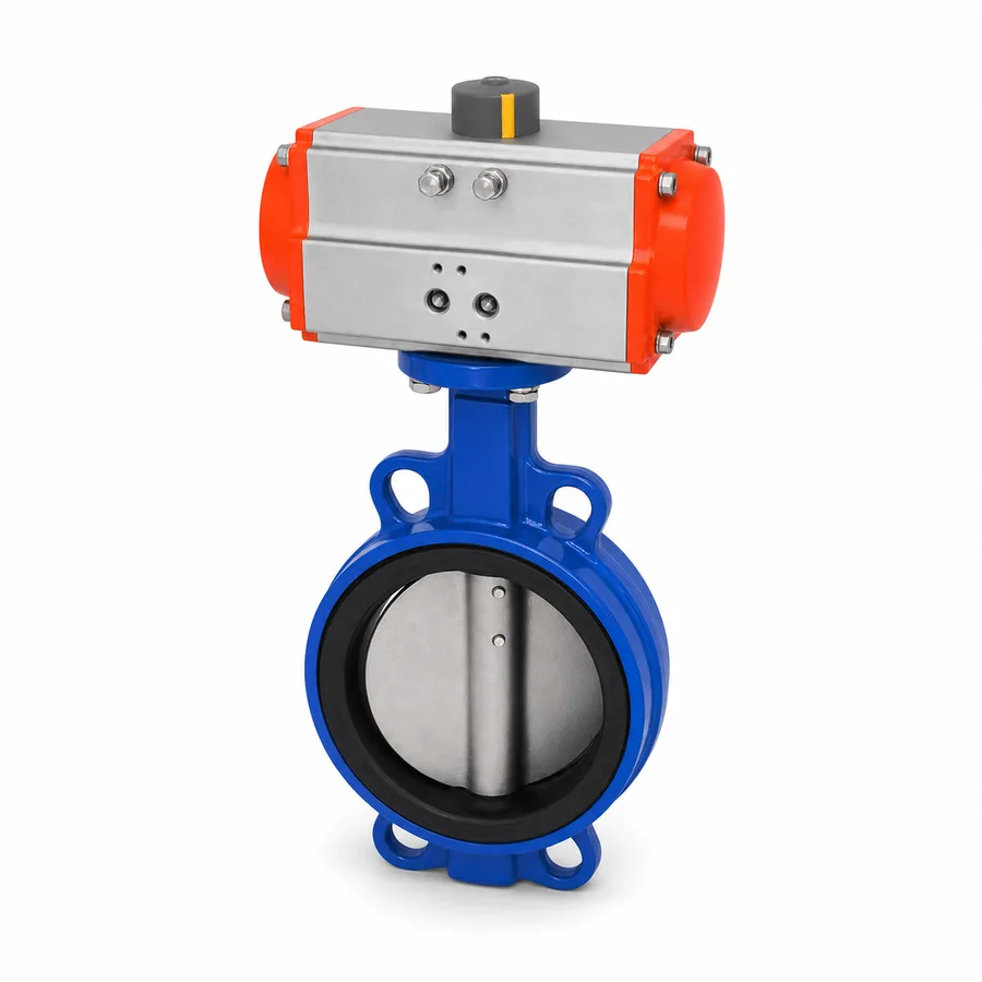
Automated wafer butterfly valve — pneumatic or electric actuator on an ISO 5211 interface
TECTUL · Dispatch across Colombia · Exports to Central & South America
A wafer-type butterfly valve, automated with a quarter-turn actuator —pneumatic or electric— mounted on the standardized ISO 5211 interface. This sheet does not repeat the educational content on what a butterfly valve is or the general pneumatic-versus-electric breakdown already published in the catalog's actuator blog: it focuses on the engineering datum that decides automation for this specific valve. The central point is operating torque: it is not a fixed value, it grows with size and with the line's differential pressure, and it is higher at breakaway than in motion, so the actuator is selected with a safety margin over the valve manufacturer's declared maximum torque, not over the nominal catalog torque. The sheet publishes the pneumatic-versus-electric selection table, the typical pilot pressure of instrument air, and the automation accessories —solenoid, limit switches and positioner— with their real function on the line.
Important: Before using these data in engineering, design or installation decisions on systems exposed to mechanical, pressure, rupture, fatigue, impact or water-hammer risk, it is essential to read the technical notice and limitation of liability at the end of this sheet.
SKU VT-valvula-mariposa-wafer-actuador-neumatico · 2 automation references: wafer with pneumatic actuator and wafer with electric actuator
1. Technical specifications: pneumatic versus electric
Actuator selection table
| Criterion | Pneumatic actuator | Electric actuator |
|---|---|---|
| Power supply | Plant compressed air or a dedicated compressor, typically 4 to 8 bar (60 to 115 psi) pilot pressure | Electric power —voltage and phase depending on reference (single-phase or three-phase, AC or DC depending on model)— |
| Operating time | Fast, on the order of seconds for a full quarter-turn | Slower, from several tens of seconds to minutes depending on torque and motor |
| Fail-safe | Single-acting with spring return: closes or opens by itself, with no air needed, on loss of power. Double-acting: requires air on both strokes and has no inherent fail-safe position | Requires a backup battery or a dedicated mechanical mechanism (emergency spring) to achieve fail-safe; not present by default on most models |
| Operating cycles | Suitable for frequent cycles; main wear is on the pneumatic seals and the control solenoid valve | Suitable for frequent cycles with caution on the motor and gearbox —check the manufacturer's duty cycle rating—; very frequent cycling may require a continuous-duty model |
| Ingress protection (IP) | Housing usually IP65 or higher depending on manufacturer; not very sensitive to ambient temperature in the typical process range | Housing usually IP65 or higher; the electronic control module may have stricter ambient temperature limits than the pneumatic one |
| Required power availability | Requires instrument-quality compressed air available at the installation point | Requires an electrical feed at the installation point; preferable where no compressed air network exists |
| Mounting interface | ISO 5211, F05 to F16 flange depending on valve size | ISO 5211, same flange family as the pneumatic one |
Both references share the same base wafer valve (ductile iron sheet FT-TC-VAL-MARIP-HD-001): what changes is the actuator and its accessories. The exact torque of each actuator model, its certified operating time and its IP rating are confirmed on quotation with the actuator manufacturer's data sheet, which in most cases is a different supplier from the valve's.
⚠ Important: this technical data sheet is a reference guide to the product's properties; it is not a quality certificate for the product you are buying. Heats vary from one another and may differ from the values stated here, or even depart from the standards. If your application requires compliance with a standard, always check the quality certificate (mill certificate) of the lot you are buying. If in doubt, ask one of our technical advisors →
2. ISO 5211 interface and the safety margin over operating torque
The actuator —pneumatic or electric— is not selected by the valve's nominal catalog torque, but by the real maximum torque that valve demands under the project's operating conditions, with a safety margin. This is the rating criterion specific to an automated valve, different from the pressure or temperature criterion of manual valve sheets.
Why torque is not a single number
A butterfly valve's operating torque combines disc-to-seat friction, shaft seal friction and the hydrodynamic torque the flow exerts on the disc (same physical principle as the ductile iron sheet, section 4). All three grow with size, and the hydrodynamic one grows further with the line's real differential pressure (ΔP) at the moment of operation —which is not necessarily the valve's design pressure—. And within a single opening or closing cycle, torque is not constant: breakaway torque, needed to start motion from the closed or open position, is higher than running torque in motion —automation practice documents that running torque can be 40 to 60 % lower than breakaway—.
Selection safety margin
- Take the maximum torque declared by the valve manufacturer for the size and the real service ΔP —not the torque from a generic catalog at a different size or ΔP—.
- Apply a usual safety margin of 1.25 to 1.5× over that maximum torque to select the actuator's nominal output torque: automation practice documents this range as protection against real-world deviations —seat wear, scale buildup, supply air pressure variation— from the theoretical calculation.
- Verify that the actuator delivers that nominal torque at the minimum expected pilot pressure on site, not just at the actuator's design pressure, because a drop in the plant's air supply pressure directly reduces available torque.
- The exact torque value by size for this line, and the certified nominal torque of each reference's actuator, are confirmed on quotation with both manufacturers' data sheets.
This 1.25 to 1.5× margin is a documented valve automation industry practice, not a figure from a single standard: it is consistently cited in actuator manufacturers' technical literature as a safe sizing criterion against real operating uncertainty.
3. Pneumatic pilot pressure and electric drive
Pneumatic actuator pilot pressure
This line's pneumatic actuator operates on instrument air —dry, clean and at regulated pressure— in a typical range of 4 to 8 bar (60 to 115 psi) pilot pressure. This datum has two direct design consequences:
- Air quality: air with moisture or particles accelerates wear on the actuator's internal seals and on the control solenoid valve; a filter-regulator on the supply is a standard precaution, not optional, on permanent installations.
- Pressure stability: since the actuator's output torque depends on the real pilot pressure (section 2), an air network with frequent pressure drops reduces the available torque below the calculated value. Verifying the network's real minimum pressure at the installation point, not just at the compressor, is part of correct sizing.
Electric drive
The electric actuator integrates motor, gearbox and control in a single assembly, with no need for a compressed air network at the installation point —its advantage over the pneumatic one where that network does not exist or is expensive to run—. As a trade-off, its operating time is slower and, on installations with no backup battery, it offers no automatic fail-safe position on power loss: the valve stays in the position it was in at the moment of the outage, unless the model includes a dedicated emergency mechanism.
Summary selection criterion
| Choose pneumatic when | A compressed air network already exists on site, fast operation is needed, or the process requires an economical and reliable fail-safe position (spring) |
| Choose electric when | No compressed air network is available or it is expensive to install, the point is far from the compressor room, or fine integrated position control is required with no additional pneumatic instrumentation |
This sheet does not repeat the general educational pneumatic-versus-electric discussion —already published in the catalog's actuator blog—: it is limited to the criterion applied specifically to this line's wafer butterfly valve and its real operating torque.
4. Automation accessories: solenoid, limit switches and positioner
| Pilot solenoid | A small electropneumatic valve that directs control air to one or the other chamber of the pneumatic actuator according to the received electrical signal (on/off or 24 VDC/110-220 VAC depending on model). It is the element that converts an electrical command signal into pneumatic motion; double-acting actuators typically require two solenoid ways, single-acting spring-return ones only one. |
| Limit switches | Mechanical or proximity switches that signal the control system whether the disc has reached the open or closed position. This is the datum that confirms remotely that the operation was actually executed, not just that the command was sent —a critical distinction in automated processes where the valve can get stuck without the system knowing, if there is no position feedback—. |
| Positioner | A module that compares the disc's real position (feedback) with a continuous reference signal (e.g. 4-20 mA) and adjusts the actuator to hold that intermediate position precisely, enabling modulating throttling instead of only full open/closed operation. Added when the process needs to regulate flow continuously, not just shut off or open. |
When each accessory is needed
- On-off service: solenoid and limit switches are practically standard on any remote automation; without limit switches, the operator loses confirmation of the real position.
- Throttling (modulating) service: in addition to the above, a positioner is required, and it is worth checking with the valve manufacturer whether this line's disc and seat design is validated for continuous throttling or only for shut-off —a concentric elastomeric-seat butterfly valve accepts partial throttling, but with the same cavitation caveats at small openings documented in the ductile iron sheet (section 4)—.
- Safety redundancy: on processes where the fail-safe position is critical, verify whether the single-acting spring-return actuator covers the case, or whether a backup battery (on the electric one) is also required to guarantee movement to the safe position on power loss.
5. Frequently asked questions
What safety margin should I apply over the valve's torque when selecting the actuator?
Between 1.25 and 1.5× over the maximum torque declared by the valve manufacturer for the real size and ΔP of service, not over a generic catalog torque. This is documented practice in the valve automation industry against real operating uncertainty.
Why is breakaway torque higher than running torque?
Because starting motion from the closed or open position requires overcoming the disc's static friction against the seat, which is higher than dynamic friction once the disc is already moving. Automation practice documents that running torque can be 40 to 60 % lower than breakaway.
What air pressure does the pneumatic actuator need?
Typical pilot pressure of 4 to 8 bar (60 to 115 psi) of dry, clean instrument air. A drop in network pressure directly reduces the actuator's available torque below the calculated value, so verify the real minimum pressure at the installation point, not just at the compressor.
Does the electric actuator close by itself on a power outage?
Not by default. Most electric actuators have no inherent fail-safe: the valve stays in the position it was in at the moment of the outage, unless the model includes a backup battery or a dedicated emergency mechanism. Spring fail-safe is a feature of the single-acting pneumatic actuator.
Do I need a positioner if I am only shutting off flow, not regulating it?
No. The positioner is needed for modulating throttling with continuous position feedback; for on-off service, a solenoid and limit switches are enough to command and confirm the open/closed position.
6. Application notes
Feasibility
This line covers remote opening and closing, and modulating throttling with a positioner, in water, air and fluid services compatible with the base valve's seat (ductile iron sheet FT-TC-VAL-MARIP-HD-001). Choose pneumatic when a compressed air network already exists and fast operation or an economical spring fail-safe is needed; choose electric when no air network is available or the point is far from the compressor room. It is not the choice when the service requires electric fail-safe with no backup battery installed, or when the line's real torque exceeds the selected actuator's maximum. For critical or safety applications, consult our technical team before specifying.
Installation
Mount the actuator on the correct ISO 5211 flange for the valve's size, checking the shaft coupling before tightening. On pneumatic units, install a filter-regulator on the air supply and verify the network's real minimum pressure at the installation point. On electric units, check the supply voltage and phase against the actuator's nameplate before energizing. Wire limit switches and the solenoid per the manufacturer's diagram, and test the full open/close cycle with no line pressure before putting the line into service, confirming that position signals reach the control system correctly.
Design
Calculate the valve's real maximum torque for the size and service ΔP before selecting the actuator, and apply the 1.25 to 1.5× margin over that value (section 2), not over a generic catalog torque. Define from the design stage whether the service is on-off or modulating, because it changes the required accessories (positioner, section 4) and may change the base valve's seat suitability for continuous throttling. If fail-safe is a process requirement, decide between a pneumatic spring or an electric backup battery from the specification stage, not as a last-minute accessory. Verify real compressed air or electrical feed availability at the exact installation point before committing to an actuator technology.
7. Technical notice and limitation of liability
The materials and regulatory framework in this sheet combine API 609 and MSS SP-67 (base valve type) and ISO 5211 (actuator interface), with the data TECTUL publishes on each product page (actuator type) and documented valve automation industry practice (torque safety margin, breakaway-to-running torque ratio). They do not constitute a certificate of conformity for any production lot.
The 1.25 to 1.5× safety margin over torque and the 40 to 60 % difference between breakaway and running torque cited in section 2 are documented actuator manufacturer practice, not a figure from a single standard: the exact torque by size and ΔP for this line, and the certified nominal torque of each actuator, are confirmed on quotation with the valve manufacturer's and the actuator manufacturer's data sheets —usually different suppliers—.
These values must not be used as the sole criterion in critical, safety, certified fail-safe applications, or wherever automation failure may compromise people, property or the environment: in such cases the control and safety system design belongs to the responsible engineer of the project. Before deciding with these data, consult our technical team.
Sources
- API 609 — Butterfly Valves: Double-Flanged, Lug- and Wafer-Type: tipo de válvula base de esta referencia automatizada
- MSS SP-67 — Butterfly Valves: requisitos generales de diseño de la válvula base
- ISO 5211 — Industrial valves — Part-turn actuator attachments: interfaz de montaje de actuador, bridas F05 a F16
- Literatura técnica de fabricantes de actuadores de cuarto de vuelta: margen de seguridad de 1,25 a 1,5× sobre el par máximo de la válvula, y relación entre par de arranque (breakaway) y par de operación en movimiento
- Ficha técnica FT-TC-VAL-MARIP-HD-001 (mariposa hierro dúctil, catálogo TECTUL): física del par de maniobra (fricción disco-asiento, sellos de eje, par hidrodinámico) aplicada a la válvula base de esta ficha
- Fichas de producto TECTUL (tectul.com): Válvula Mariposa Wafer Con Actuador Neumático y Válvula Mariposa Wafer Con Actuador Eléctrico — fuente de material declarado y norma de interfaz
This data sheet is the property of TECTUL, part of the Industrias IMR group. Reproduction without attribution is prohibited. Original document and updates: tectul.com/en/conduccion-de-fluidos/valvulas/ficha-tecnica-valvula-mariposa-wafer-actuador-neumatico.html.