 TECTULby IMR
Metal-body foot valves and suction check valves
TECTUL · Dispatch across Colombia · Exports to Central & South America
This sheet covers the 10 metal-body foot valve and suction check valve references in the TECTUL catalog: cast bronze with bronze basket, with fine bronze mesh or with plastic strainer, aluminum, brass and flanged iron, from 3/8″ to 6″. There is no single international pressure-rating standard for this family: each manufacturer declares its own, and the quantity that actually governs selection is not pressure but head loss, because it is deducted directly from the pump's available NPSH. This sheet publishes what no local distributor puts on the commercial listing: how much head a poppet-type foot valve loses compared with a hinged-disc check, how that value is deducted from NPSH with a worked example, why the valve is sized by seat velocity and not by pipe diameter, and what minimum submergence it requires so as not to draw air.
Important: Before using these data in engineering, design or installation decisions on systems exposed to mechanical, pressure, rupture, fatigue, impact or water-hammer risk, it is essential to read the technical notice and limitation of liability at the end of this sheet.
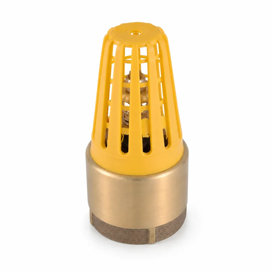
SKU VT-59221 (Helman yellow plastic-basket foot valve, 1″-4″) · metal block of 10 references, 3/8″ to 6″ (flanged iron, hose-end check and deep-well check confirmed on quotation)
1. Technical specifications: 10 metal-body references
A foot valve is a check valve with an integral strainer installed at the submerged end of the suction pipe: it holds the water column when the pump stops —keeping the line primed— and stops coarse solids before they enter the system. This family has no single international pressure-rating standard: there is no ASME class or WOG/CWP system behind it, each manufacturer declares its own per reference. Its real design quantity is not pressure but head loss (section 2). Where the manufacturer publishes no figure, this sheet states «confirmed on quotation» instead of estimating it.
| Type | Check valve with integral strainer, for the submerged end of the suction line |
| Bodies in the metal block | Cast bronze, aluminum, brass and cast iron |
| Bronze designation | Not published per reference by the manufacturer; the usual designation for cast bronze in threaded valves is ASTM B62 — confirmed on quotation |
| Strainers | Bronze basket, fine bronze mesh or plastic strainer mounted on a bronze body |
| Closing disc | Poppet type (guided vertical disc, gravity closing) on the catalog threaded references |
| Ends | NPT thread (ASME B1.20.1) across the threaded block; cast iron in the flanged version |
| Rating system | None international. Design quantity: head loss and seat velocity |
| Typical service | Cold water from cisterns, wells, rivers or tanks; suction of centrifugal pumps and portable pumps |
| Mounting position | Vertical or up to 45° from vertical (gravity closing) |
1.1 Metal-body references in the TECTUL catalog
| Reference | Body | Strainer | Published sizes | Connection |
|---|---|---|---|---|
| Aluminum foot valve | Aluminum | Integral basket | 1″ · 1-1/4″ · 1-1/2″ · 2″ · 3″ · 4″ · 6″ (7) | NPT threaded |
| Napoli bronze foot valve | Bronze | Bronze basket | 3/8″ · 1/2″ (2) | NPT threaded |
| Helman bronze-basket foot valve | Cast bronze | Bronze basket | 1″ · 1-1/4″ · 1-1/2″ · 2″ · 3″ · 4″ · 6″ (7) | NPT threaded |
| Helbert bronze-mesh foot valve | Cast bronze | Fine bronze mesh | 3/4″ · 1″ · 1-1/4″ · 1-1/2″ · 2″ (5) | NPT threaded |
| Helman yellow plastic-basket foot valve | Bronze | Plastic strainer | 1″ · 1-1/4″ · 1-1/2″ · 2″ · 2-1/2″ · 3″ · 4″ (7) | NPT threaded |
| Helbert red plastic-basket foot valve | Bronze | Plastic strainer | 3/4″ · 1″ · 1-1/4″ · 1-1/2″ · 2″ · 2-1/2″ (6) | NPT threaded |
| Helman red plastic-basket foot valve (light) | Bronze | Plastic strainer | 3/4″ · 1″ · 1-1/2″ · 2″ (4) | NPT threaded |
| Flanged iron foot valve | Cast iron | Filtering basket | Confirmed on quotation | Flanged |
| Brass hose-end (grenade) check | Brass | Filtering basket | Confirmed on quotation | Female hose thread |
| Deep-well check valve | Bronze | No strainer (pure retention) | Confirmed on quotation | Threaded |
IMPORTANT
This data sheet is a reference guide to the properties of this product type. The measurements, dimensions and physical or geometric characteristics of the product actually supplied may vary by manufacturer and lot, and may even fall outside the cited standards. If any of these figures is critical to your design or build, it is essential to verify it with one of our advisors against the physical product, so you can be fully certain of what you are buying. · Original data sheet: tectul.com/en/conduccion-de-fluidos/valvulas/ficha-tecnica-valvula-pie-canastilla-plastica-amarilla.html
The «Napoli bronze foot valve» reference has a title inconsistency in the catalog's internal record: it appears as «Check Retención Hierro» (iron retention check) even though it is classified with bronze material and has its own variants (3/8″ and 1/2″). The material and type published here are those of that reference's variant record — to be confirmed with the sales team before quoting. PVC-body foot valves of the same line (PVC foot valve, and PVC air-release and foot valve) are not in this sheet: they are in FT-TC-VAL-PIE-PVC-001.
1.2 Three strainer constructions, three different services
| Construction | What it retains | When to specify it |
|---|---|---|
| Bronze basket | Coarse solids: leaves, stones, floating debris | General service in cisterns, rivers or open tanks. The most robust construction: the basket is the same metal as the body and withstands mechanical impact |
| Fine bronze mesh | Coarse solids plus sand and fine sediment | Water with suspended sand or wells carrying fines, where sediment damages the seal and the impeller. It clogs faster: it requires more frequent cleaning |
| Plastic strainer on a bronze body | Coarse solids; the metal body still provides the seat and the thread | When weight and cost matter but the metal seat must be kept. The plastic strainer is the sacrificial part: it is replaced without changing the valve, and it does not corrode in aggressive water |
⚠ Important: this technical data sheet is a reference guide to the product's properties; it is not a quality certificate for the product you are buying. Heats vary from one another and may differ from the values stated here, or even depart from the standards. If your application requires compliance with a standard, always check the quality certificate (mill certificate) of the lot you are buying. If in doubt, ask one of our technical advisors →
2. Head loss and NPSH: the foot valve's design quantity
2.1 Combining check and strainer costs head — a lot of it
The foot valve has no governing pressure rating: its design quantity is head loss, because it is deducted directly from the pump's available NPSH. The disc geometry determines how much. The poppet type (guided vertical disc, the most common in catalog threaded foot valves, including the 7 threaded references in this sheet) has an equivalent length of L/D = 420 pipe diameters; the hinged or swing-disc check has L/D = 75 — nearly six times less. Both values come from the equivalent-length table of Crane Technical Paper No. 410, the classic reference for minor losses in piping.
Translated into a field figure: a manufacturer's sizing guide reports that at a design velocity of 2 m/s at the seat, a poppet-type foot valve generates between 0.3 and 0.6 bar of loss (3 to 6 meters of water column). That is suction the pump stops receiving before the water even enters the pipe.
2.2 Worked example: how much NPSH the foot valve takes
- Impeller centerline 3 m above the minimum water level (negative suction: the case that requires a foot valve to avoid losing prime).
- Atmospheric pressure at sea level:
Ha = 10.33 mof water column. - Water vapor pressure at 20 °C:
Hvp ≈ 0.24 m. - Suction pipe friction (illustrative value, depends on the actual layout):
Hf(line) = 0.3 m. - Poppet-type foot valve loss, midpoint of the 3-6 m range:
Hf(valve) = 4.5 m. Available NPSH = Ha − Hs − Hvp − Hf(line) − Hf(valve) = 10.33 − 3 − 0.24 − 0.3 − 4.5 ≈ 2.3 m
The exercise does not replace the calculation of the actual system —which requires the specific pump's required-NPSH curve and the exact line losses— but it shows the size of the problem: the foot valve alone consumes almost half of the available suction margin in this case. Hence, in marginal negative suction, the first design levers are switching to a hinged-disc check (L/D = 75) instead of poppet (L/D = 420), or moving up one size to lower seat velocity — before touching the pump.
2.3 Size it by seat velocity, not by pipe diameter
The most common selection error is choosing the foot valve by the nominal pipe diameter. The correct rule is the flow velocity through the seat: between 0.5 and 1.0 m/s. Below that range the valve may not close properly —the disc does not seat with enough force—; above it, head loss rises fast and can consume the available NPSH. The strainer, in addition, must have between 3 and 5 times the pipe cross-sectional area so that it does not itself become the assembly's greatest restriction. That is why a catalog foot valve is physically much bulkier than a check valve of the same nominal size.
2.4 Minimum submergence: why it cannot sit on the bottom or near the surface
If the water level is too close to the valve inlet, the suction forms a surface vortex that draws air into the pipe; air in the suction causes loss of prime, noise, vibration and intermittent cavitation. The manufacturer's sizing guide sets the practical rule: minimum submergence ≥ 2 times the valve's nominal diameter, measured from the minimum water level to the valve inlet. On the other side, the valve cannot rest on the bottom either: it needs clearance so water enters through the full strainer area and so it does not draw up settled sediment. In larger suction structures (sumps, high-flow pumping wells) the industry criterion is ANSI/HI 9.8, Rotodynamic Pumps for Pump Intake Design from the Hydraulic Institute, which also incorporates approach velocity and the Froude number — outside the scope of a catalog valve and the domain of the project engineer.
3. Material by service, mounting and special suction variants
3.1 Which metal for which service
| Body | Why it is chosen | Practical limit |
|---|---|---|
| Cast bronze | The reference construction for water suction: it holds up well against fresh water and seat wear, and gives a firm NPT thread. It is the body of 5 of the 10 references in this sheet | It corrodes in brackish water and in water with agricultural chemicals or dissolved fertilizers: there the option is the PVC body (FT-TC-VAL-PIE-PVC-001) |
| Aluminum | Far lighter than bronze in large sizes (up to 6″). Used where the valve is installed and removed by hand, or where the weight hanging from the pipe matters | Lower mechanical and galvanic-corrosion resistance than bronze; do not combine with copper piping without dielectric isolation |
| Brass | Body of the hose-end (grenade) check: light, economical and threaded for a hose coupling | Portable service, not permanent |
| Cast iron (flanged) | The block's only option for large suction sizes with a flanged connection, where threading is no longer practical | Weight and need for its own support; requires compatible flanges and gaskets. Sizes confirmed on quotation |
3.2 Mounting orientation
The poppet disc relies on gravity to close: the valve must be installed vertical or with a maximum tilt of 45° from vertical. In a horizontal position, closing is not reliable unless the manufacturer confirms an assist spring. Also: the valve must never rest on the bottom of the well or cistern, and the suction line must rise on a continuous slope toward the pump (with no intermediate high points) so that air does not become trapped in a pocket and break the prime.
3.3 The three special suction variants in this block
| Variant | Where it mounts | When it is used |
|---|---|---|
| Foot valve with strainer | Fixed, submerged end of the suction pipe, vertical or up to 45° | General case: permanent suction from a cistern, well or tank, with risk of solids in the water |
| Brass hose-end (grenade) check | End of the flexible suction hose | Portable pumps and mobile equipment: it is removed and stored with the hose; the strainer is integral to the same body |
| Deep-well check valve | Directly on the submersible pump's discharge thread or flange, inside the borehole | Deep wells with a submersible pump: it holds the water column of the entire borehole pipe and protects the equipment from hydraulic backlash at shutdown. It carries no strainer: it is pure retention |
3.4 Maintenance
The strainer is the first part to clog with sediment, algae or sand. Cleaning it periodically prevents the actual restriction from exceeding the 0.5-1.0 m/s design range and spiking the head loss. A progressive drop in flow or intermittent cavitation with no changes in the system is the typical sign of a dirty strainer or a disc that no longer seats. On the plastic-basket references, the basket is the sacrificial part and is replaced without changing the bronze body. When dismantling, always wrench on the metal body, never on the basket or the mesh.
4. Frequently asked questions
How many psi does a bronze foot valve withstand?
There is no catalog answer: this family has no international pressure-rating standard and none of the manufacturers of the references in this sheet publish a working pressure per size. That is consistent with its function: the foot valve works submerged at the suction end, where pressure is low and what governs design is head loss, not pressure. If the specification requires a declared pressure value, it is confirmed on quotation with the supplier per reference and lot.
How deep should the foot valve sit?
With a minimum submergence of at least 2 times the valve's nominal diameter, measured from the minimum water level to the valve inlet, and without resting on the bottom. Less submergence encourages the surface vortex that draws air, causing loss of prime and intermittent cavitation; resting on the bottom draws up settled sediment and clogs the strainer quickly.
Poppet or hinged disc: which loses less head?
The hinged disc, by a wide margin: L/D = 75 versus L/D = 420 for the poppet, per the equivalent-length table in Crane TP-410 — nearly six times less. In marginal negative suction, where every meter of NPSH counts, switching from poppet to hinged disc is one of the first design levers, before changing the pump.
How do I choose the foot valve size?
By flow velocity at the seat (0.5-1.0 m/s), not by the nominal pipe diameter. It is normal for the valve to end up one size above the suction line: that lowers velocity, lowers loss and protects NPSH. Also check that the strainer area is 3 to 5 times the pipe cross-section.
Bronze basket or plastic strainer?
Both filter coarse solids and share the bronze body and seat. The bronze basket is more robust against mechanical impact and lasts longer in permanent service; the plastic strainer is lighter, cheaper, does not corrode and is a sacrificial part replaced without changing the valve. If the water carries suspended sand, neither: use the fine bronze mesh, accepting that it requires more frequent cleaning.
Does a foot valve work for a deep well with a submersible pump?
It is not the same part. A deep well with a submersible pump uses the deep-well check valve, installed on the pump itself inside the borehole and with no strainer. The foot valve is for surface suction: cistern, tank, river or well with a surface pump. Both hold the water column, but they mount at different points of the system.
5. Application notes
Feasibility
For general water suction in cisterns and surface tanks, the bronze foot valve with plastic strainer (Helman or Helbert, 3/4″-4″) covers the catalog's standard service. In water with sand or fine sediment, the bronze mesh basket filters better at the cost of more frequent cleaning. Where weight matters or the size reaches 6″, the aluminum body is the alternative. For large-diameter suction with a flanged connection, cast iron is the block's only option — sizes confirmed on quotation. For portable pumps, the brass hose-end check goes at the hose end, and for a deep well with a submersible pump the deep-well check applies, not the foot valve. If the fluid is brackish water or carries agricultural chemicals or fertilizers, none of these metal references applies: the option is the PVC body in FT-TC-VAL-PIE-PVC-001.
Installation
Install the foot valve vertical or up to 45° from vertical, with minimum submergence of 2 times its nominal diameter, without resting it on the bottom, and with seat velocity within 0.5-1.0 m/s. The suction pipe must rise on a continuous slope toward the pump, with no high points where air can be trapped. Seal the NPT thread (ASME B1.20.1) with PTFE tape or a compatible sealant; always wrench on the metal body, never on the basket or the mesh. Check that the strainer's free area is 3 to 5 times the pipe cross-section and schedule strainer cleaning as periodic maintenance, not as a reaction to failure.
Design
In negative suction, calculate the available NPSH including the foot valve's loss (0.3-0.6 bar at 2 m/s for the poppet type) in addition to line friction, not just static lift and vapor pressure; compare it against the specific pump's required-NPSH curve, with the margin set by the project criteria. If the margin is tight, move up one size to lower seat velocity or specify a hinged disc (L/D = 75) instead of poppet (L/D = 420) before changing the pump. In suction structures larger than a catalog valve, the submergence and vortex-control criterion is ANSI/HI 9.8, not this sheet's 2-diameter rule. None of these values replaces the project's hydraulic design under the code governing the installation.
6. Technical notice and limitation of liability
The sizes and materials in this sheet are catalog values declared by TECTUL from its own variant records (Jul-Aug 2026 list). This family has no single international pressure-rating standard: each manufacturer sets its own and, for the references in this sheet, none publishes a working pressure per size. These data guide selection; they are not a certificate of conformity for any given unit nor independent testing by TECTUL.
The head-loss values (L/D = 420 poppet and L/D = 75 hinged disc from Crane TP-410; 0.3-0.6 bar at 2 m/s), the design seat velocity, the strainer area and the minimum submergence are reference values from technical literature and a manufacturer's guide, not measurements on the units sold. Each valve's actual loss depends on its internal geometry, the strainer condition and the flow regime.
The NPSH example in section 2 uses standard physical values (atmospheric pressure at sea level, water vapor pressure at 20 °C) and illustrative line-friction values; it does not replace the calculation of the actual system, which requires the specific pump's required-NPSH curve. These values must not be used as the sole criterion in critical or safety applications, nor wherever suction failure may compromise people, property or the environment: in such cases the design belongs to the project's responsible engineer. Before deciding with these data, consult our technical team.
Sources
- Crane Co., Technical Paper No. 410 — Flow of Fluids Through Valves, Fittings and Pipe: tabla de longitud equivalente (L/D) para válvula de pie con colador, disco tipo poppet (L/D = 420) y disco articulado o de bisagra (L/D = 75)
- Hydraulic Institute — ANSI/HI 9.8, Rotodynamic Pumps for Pump Intake Design: criterio de sumergencia mínima y control de vórtice en estructuras de succión de mayor escala que una válvula de catálogo
- Guía técnica de selección y dimensionamiento de válvulas de pie de fabricante: velocidad de diseño en el asiento (0,5-1,0 m/s), pérdida de carga típica a 2 m/s (0,3-0,6 bar o 3-6 m.c.a.), área libre de colador (3-5× la sección de tubería), sumergencia mínima (≥ 2 diámetros nominales) y orientación de montaje vertical o hasta 45°
- ASME B1.20.1 — Pipe Threads, General Purpose (Inch): rosca NPT de los extremos roscados del bloque metálico; la tabla canónica de hilos por pulgada, L2, L4 y profundidad de filete está publicada en FT-TC-ACC-NIP-001 y no se repite aquí
- ASTM B62 — Standard Specification for Composition Bronze or Ounce Metal Castings: designación habitual del bronce fundido en válvulas roscadas; los fabricantes de estas referencias no la declaran por producto, por lo que aquí se cita como referencia y se confirma al cotizar
- Catálogos y fichas de los fabricantes Helman y Helbert (marcas distribuidas por TECTUL) — configuraciones de colador (canasta de bronce, malla fina de bronce, canastilla plástica) y diámetros disponibles por referencia de válvula de pie
- Valores físicos estándar de presión atmosférica al nivel del mar (10,33 m de columna de agua) y presión de vapor del agua a 20 °C (≈ 0,24 m), usados en el ejemplo ilustrativo de NPSH de la sección 2
- data/etapas/etapa-1-conduccion-de-fluidos/curaduria.json y data/scraped/products/*.json del catálogo TECTUL — descripciones comerciales de las 10 referencias metálicas de esta ficha (registro interno, jul-ago 2026)
This data sheet is the property of TECTUL, part of the Industrias IMR group. Reproduction without attribution is prohibited. Original document and updates: tectul.com/en/conduccion-de-fluidos/valvulas/ficha-tecnica-valvula-pie-canastilla-plastica-amarilla.html.