 TECTULby IMR
PVC-body foot valves (with and without air release)
TECTUL · Dispatch across Colombia · Exports to Central & South America
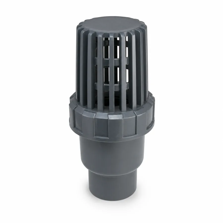
This sheet covers the two PVC-body foot valves in the TECTUL catalog: the PVC foot valve, from 3/4″ to 4″ and the most economical reference in the whole suction block, and the Tecno Plastic threaded PVC air-release and foot valve, from 1/2″ to 3″, which integrates an air release into the same body. PVC is not chosen for being cheaper: it is chosen because bronze does not withstand water with agricultural chemicals, dissolved fertilizers or brackish water, which is exactly the irrigation and intake service this valve lives in. In exchange, the material imposes two limits bronze does not have: the PVC-U maximum service temperature (60 °C, 140 °F) and the plastic thread's fragility against over-tightening. The suction physics —head loss, NPSH deduction, seat velocity and minimum submergence— is the same for the whole family and is applied here to this material.
Important: Before using these data in engineering, design or installation decisions on systems exposed to mechanical, pressure, rupture, fatigue, impact or water-hammer risk, it is essential to read the technical notice and limitation of liability at the end of this sheet.
SKU VT-59223 (PVC foot valve, 3/4″-4″, 8 published sizes) · PVC block of 2 references; the second is the Tecno Plastic threaded PVC air-release and foot valve (1/2″-3″, 6 sizes)
1. Technical specifications: the 2 PVC-body references
A foot valve is a check valve with an integral strainer installed at the submerged end of the suction line: it holds the water column when the pump stops —keeping the line primed— and stops coarse solids. In a PVC body, TECTUL publishes two references. This family has no international pressure-rating standard and neither manufacturer publishes a working pressure per size: the design quantity is head loss (section 4) and the material's hard limit is temperature (section 2). Where the manufacturer publishes no figure, this sheet states «confirmed on quotation».
| Type | Check valve with integral strainer for the submerged suction end; one of the two references also incorporates an air release |
| Body and strainer | Injection-molded PVC-U (unplasticized polyvinyl chloride) |
| Closing disc | Poppet type (guided vertical disc, gravity closing) |
| Seals | Elastomer (usually NBR or EPDM depending on the fluid) — not declared per reference by the manufacturer, confirmed on quotation |
| Ends | Threaded. 60° tapered thread for thermoplastics per ASTM F1498; compatible with metal NPT thread provided the plastic male enters the metal female |
| Maximum service temperature | 60 °C (140 °F) — the limit of the PVC-U compound, not of the valve |
| Pressure rating system | None declared by the manufacturer for these references. Confirmed on quotation |
| Typical service | Irrigation and fertigation, agricultural intake, brackish water, water with dissolved chemicals, drainage and transfer where bronze corrodes |
| Mounting position | Vertical or up to 45° from vertical (gravity closing) |
1.1 PVC-body references in the TECTUL catalog
| Reference | Body | Distinctive feature | Published sizes | Connection |
|---|---|---|---|---|
| PVC foot valve | PVC-U | Check valve with integral PVC strainer | 3/4″ · 1″ · 1-1/4″ · 1-1/2″ · 2″ · 2-1/2″ · 3″ · 4″ (8) | Threaded |
| Tecno Plastic threaded PVC air-release and foot valve | PVC-U | PVC strainer + air release integrated into the same body | 1/2″ · 3/4″ · 1″ · 1-1/2″ · 2″ · 3″ (6) | Tecno Plastic thread |
IMPORTANT
This data sheet is a reference guide to the properties of this product type. The measurements, dimensions and physical or geometric characteristics of the product actually supplied may vary by manufacturer and lot, and may even fall outside the cited standards. If any of these figures is critical to your design or build, it is essential to verify it with one of our advisors against the physical product, so you can be fully certain of what you are buying. · Original data sheet: tectul.com/en/conduccion-de-fluidos/valvulas/ficha-tecnica-valvula-pie-pvc.html
The PVC foot valve does not publish intermediate sizes other than those listed: the series is the one in the table, not a continuous series. Metal-body foot valves and suction checks (bronze, aluminum, brass, iron) are not in this sheet: they are in FT-TC-VAL-PIE-METAL-001.
1.2 When PVC and when metal
| Situation | Indicated body | Why |
|---|---|---|
| Clean fresh water, permanent suction, heavy service | Bronze (FT-TC-VAL-PIE-METAL-001) | Longer-lasting metal seat and a body that tolerates mechanical impact and installation over-tightening |
| Irrigation and fertigation with dissolved fertilizers | PVC | Bronze and brass are attacked by fertilizer solutions; PVC-U is inert to most irrigation salts and fertilizers |
| Brackish water, coastal wells, chloride-bearing intakes | PVC | Chloride attacks copper alloys (dezincification and pitting corrosion); PVC has no such failure mechanism |
| Water with process or dosing chemicals | PVC, verifying chemical compatibility of the specific fluid | PVC-U resists dilute acids and bases at ambient temperature, but not all organic solvents: verify per fluid |
| Fluid above 60 °C | Neither: metal body | 60 °C is the ceiling for PVC-U, regardless of service pressure |
⚠ Important: this technical data sheet is a reference guide to the product's properties; it is not a quality certificate for the product you are buying. Production lots vary from one another and may differ from the values stated here, or even depart from the standards. If your application requires compliance with a standard, always check the quality certificate (mill certificate) of the lot you are buying. If in doubt, ask one of our technical advisors →
2. The material's limit: 60 °C and pressure loss with temperature
PVC-U is a thermoplastic: its mechanical strength falls continuously as temperature rises, not in a step. The industry publishes that fall as derating factors on the pressure declared at 23 °C, identical for pipe, fittings and valves of the same compound. Since these two foot valves publish no base pressure at 23 °C, the table gives no psi value: it gives the fraction of the material's capacity remaining at each temperature, and above all it sets the ceiling.
| Service temperature (°C) | Service temperature (°F) | Factor on capacity at 23 °C | What it means in the field |
|---|---|---|---|
| 23 °C | 73 °F | 1.00 | Catalog reference condition |
| 27 °C | 80 °F | 0.88 | Cistern water in the sun in a warm climate: 12 % already lost |
| 32 °C | 90 °F | 0.75 | A quarter of the capacity lost |
| 38 °C | 100 °F | 0.62 | Exposed tank in the Colombian lowlands |
| 43 °C | 110 °F | 0.51 | Half the capacity. Practical limit for PVC threads |
| 49 °C | 120 °F | 0.40 | Low-pressure services only |
| 54 °C | 130 °F | 0.31 | On the edge of the material's ceiling |
| 60 °C | 140 °F | 0.22 | Absolute ceiling of PVC-U. Above it the valve does not apply, no matter how low the pressure |
IMPORTANT
This data sheet is a reference guide to the properties of this product type. The measurements, dimensions and physical or geometric characteristics of the product actually supplied may vary by manufacturer and lot, and may even fall outside the cited standards. If any of these figures is critical to your design or build, it is essential to verify it with one of our advisors against the physical product, so you can be fully certain of what you are buying. · Original data sheet: tectul.com/en/conduccion-de-fluidos/valvulas/ficha-tecnica-valvula-pie-pvc.html
The same factor table published by the standard's manufacturers for PVC-U and consistent with the rule used across the rest of TECTUL's plastic catalog (FT-TC-ACC-PVCP-001 and FT-TC-VAL-PLAST-001, not repeated here). On a foot valve the figure carries a favorable nuance: it works submerged at the suction end, where pressure is low by definition, so the critical restriction is usually not pressure but the water temperature and that of the thread above the level. The seal elastomer imposes its own ceiling (EPDM is around 100 °C and NBR lower): the lower of the two always governs, and on this valve that lower one is the PVC body at 60 °C.
What PVC does and does not solve
It does solve: corrosion. In fertigation, in chloride-bearing intakes and in brackish water, the bronze or brass body is attacked by dezincification and pitting, and the wear is invisible until the seat stops sealing and the pump loses prime. PVC-U has no such failure mechanism, which is why it is the correct —not the cheap— option in that service.
It does not solve: impact. PVC-U is rigid and brittle compared with bronze: it withstands impact poorly, as well as dragging against the cistern bottom and the weight of a poorly supported pipe hanging from its thread. Nor does it solve temperature, or prolonged ultraviolet exposure if the valve ends up out of the water at the tank's low level.
3. Plastic thread, over-tightening and the integral air release
3.1 The plastic thread seals like the metal one, but fails differently
The 60° tapered thread for thermoplastics (ASTM F1498) seals by wedging interference, just like metal NPT. The difference is the modulus of elasticity: PVC-U is orders of magnitude less rigid than steel or bronze, so the same wrench that merely tightens a metal nipple opens the body of a PVC valve. Over-tightening is the number-one cause of plastic thread failure, and on a foot valve the symptom is twofold: a leak that breaks the prime, and ovalization of the body that prevents the poppet disc from seating. The crack usually appears hours or days after installation, not during it.
| Rule | Detail |
|---|---|
| Tightening | Hand-tight to the stop, plus 1 or 2 turns with a wrench. No more. If it leaks, dismantle and reseal: do not keep tightening |
| Sealant | PTFE tape or a PVC-compatible sealant. Do not use compounds with solvents that attack PVC-U |
| Plastic-to-metal transition | Always the plastic male inside the metal female, never the reverse: a plastic female over a metal male is wedged open and bursts |
| Wrench | On the body, never on the strainer. On the air-release reference, not on the air-release body either |
| Temperature | Do not leave PVC threads in continuous service above 43 °C (110 °F) |
| Support | The suction pipe must not hang from the valve's thread: support it separately. PVC does not tolerate bending load on the threaded joint |
3.2 What the integral air release does and when it pays for itself
The block's second reference incorporates an air release (air valve) in the same foot valve body. Its function is to evacuate the air trapped in the suction column when priming the pump, and to evacuate it again each time the line fills after a stop.
The problem it solves: when starting a pump on an empty or partly empty pipe, the column's air does not leave by itself. It stays compressed at the high points and forms an air lock: the pump turns, takes no water, runs dry and can damage the mechanical seal. With the air release, that air has a way out while the water rises, and the column fills completely. When the water reaches the air release, the float or closing element seals it and the valve keeps working as an ordinary foot check.
When it justifies the extra cost over the plain PVC foot valve (about 2.7 times costlier): on long suction lines, with irregular routing or high points, in installations that start and stop frequently, and in irrigation systems where manual priming with a bucket is impractical. On a short, straight suction from a cistern, the plain PVC foot valve does the job.
4. Suction physics applied to the PVC body
4.1 The design quantity is head loss, not pressure
As in the metal block, the PVC foot valve is sized by what it takes away from the suction, not by what it withstands. The poppet disc —the type on both of these references— has an equivalent length of L/D = 420 pipe diameters per the Crane Technical Paper No. 410 table; the hinged or swing-disc check has L/D = 75, nearly six times less. As a field figure, a manufacturer's sizing guide reports that at 2 m/s at the seat, the poppet-type foot valve generates between 0.3 and 0.6 bar (3 to 6 meters of water column) of loss.
4.2 Worked example: how much NPSH the valve takes
- Impeller centerline 3 m above the minimum water level (negative suction: the case that requires a foot valve to avoid losing prime).
- Atmospheric pressure at sea level:
Ha = 10.33 mof water column. - Water vapor pressure at 20 °C:
Hvp ≈ 0.24 m. - Suction pipe friction (illustrative value, depends on the actual layout):
Hf(line) = 0.3 m. - Poppet-type foot valve loss, midpoint of the 3-6 m range:
Hf(valve) = 4.5 m. Available NPSH = Ha − Hs − Hvp − Hf(line) − Hf(valve) = 10.33 − 3 − 0.24 − 0.3 − 4.5 ≈ 2.3 m
The exercise does not replace the calculation of the actual system —which requires the specific pump's required-NPSH curve and the exact line losses— but it sets the magnitude: the foot valve alone consumes almost half of the suction margin in this case. If the reservoir sits at higher altitude above sea level, Ha drops and the margin narrows further: on the Colombian high plateau that term is no longer 10.33 m and must be corrected for altitude before concluding anything.
4.3 Choose by seat velocity, not by pipe diameter
The most common selection error is ordering the foot valve in the same size as the pipe. The correct rule is the flow velocity through the seat: 0.5 to 1.0 m/s. Below that, the poppet disc may not seat with enough force and the valve drips at shutdown; above it, loss rises fast and eats the NPSH. The strainer must also have between 3 and 5 times the pipe cross-sectional area so that it is not itself the dominant restriction. It is normal and correct for the valve to end up one size above the line: the PVC series in this sheet publishes 8 sizes precisely to allow that.
4.4 Minimum submergence and mounting
Minimum submergence ≥ 2 times the valve's nominal diameter, measured from the minimum water level to the valve inlet. With less, the suction forms a surface vortex that draws air: loss of prime, noise, vibration and intermittent cavitation. On the other side, the valve must not rest on the reservoir bottom: it needs clearance so that water enters through the full strainer area and so that it does not draw up settled sediment. In larger suction structures (sumps, high-flow pumping wells) the industry criterion is ANSI/HI 9.8, Rotodynamic Pumps for Pump Intake Design, which incorporates approach velocity and the Froude number.
The poppet disc closes by gravity: the valve is installed vertical or with a maximum tilt of 45° from vertical. Horizontally, closing is not reliable unless the manufacturer confirms an assist spring. The suction line must rise on a continuous slope toward the pump, with no high points to trap air — and if the routing forces them, that is exactly the installation that justifies the air-release reference from section 3.
5. Frequently asked questions
How many psi does a PVC foot valve withstand?
Neither manufacturer in this sheet publishes a working pressure per size, and this family has no international pressure-rating standard. That is consistent with the function: the valve works submerged at the suction end, where pressure is low and what governs design is head loss. What is a firm material limit is temperature: 60 °C (140 °F). If the specification requires a declared pressure value, it is confirmed on quotation per reference and lot.
PVC or bronze foot valve?
PVC when the fluid corrodes metal: irrigation with dissolved fertilizers, brackish water, chloride-bearing wells, water with dosing chemicals. Bronze when the service is clean fresh water, permanent and mechanically demanding, because the metal seat lasts longer and the body better tolerates impact and tightening. Cost should not be the criterion: the PVC foot valve is the catalog's cheapest reference, but it is specified by chemistry.
What is the air release on the Tecno Plastic reference for?
It evacuates the air trapped in the suction column when priming the pump and each time the line refills after a stop. Without it, that air stays compressed at the high points and forms an air lock: the pump turns, takes no water and runs dry. It is justified on long or irregularly routed suction lines and in installations that start and stop frequently. On a short, straight suction, the plain PVC foot valve is enough.
How hard do I tighten a PVC foot valve?
Hand-tight to the stop, plus 1 or 2 turns with a wrench, with PTFE tape or a PVC-compatible sealant. No more. Over-tightening is the number-one cause of plastic thread failure and on a foot valve it produces two failures at once: a leak that breaks the prime and ovalization of the body that prevents the disc from seating. In a transition to metal, the plastic male always goes inside the metal female, never the reverse. And always wrench on the body, never on the strainer.
Does it work for hot water or a warm process?
Not above 60 °C (140 °F): that is the PVC-U ceiling and above it the valve does not apply, no matter how low the pressure. For threads in continuous service the practical limit drops to 43 °C (110 °F). Above those values a metal body applies (FT-TC-VAL-PIE-METAL-001).
How deep should the valve sit?
With minimum submergence of at least 2 times its nominal diameter from the minimum water level, and without resting on the bottom. With less submergence the suction forms a surface vortex and draws air, causing loss of prime and intermittent cavitation; resting on the bottom it draws up sediment and clogs the strainer quickly.
6. Application notes
Feasibility
The PVC foot valve (3/4″-4″, 8 sizes) is the correct option —not merely the economical one— in irrigation and fertigation with dissolved fertilizers, in chloride-bearing intakes and in brackish water, where the bronze or brass body is attacked by dezincification and pitting. The air-release and foot valve reference (1/2″-3″) is justified when the suction line is long, irregularly routed or has high points, or when the equipment starts and stops frequently: the air release prevents the air lock that makes the pump run dry. Neither applies above 60 °C nor where the valve receives mechanical impact, dragging against the bottom or bending load from a poorly supported pipe: in those cases, the metal body of FT-TC-VAL-PIE-METAL-001. PVC-U chemical compatibility with the specific fluid is verified before specifying: it resists dilute acids and bases at ambient temperature, but not all organic solvents.
Installation
Tighten hand-tight to the stop plus 1 or 2 turns with a wrench, using PTFE tape or a PVC-compatible sealant; if it leaks, dismantle and reseal instead of tightening further. In a transition to metal, the plastic male always goes inside the metal female. Wrench on the body, never on the strainer or on the air-release body. Support the suction pipe separately: it must not hang from the valve's thread. Install vertical or up to 45° from vertical, with minimum submergence of 2 times the nominal diameter, without resting it on the bottom and with seat velocity within 0.5-1.0 m/s. The suction line rises on a continuous slope toward the pump; if the routing forces high points, specify the air-release reference. Clean the strainer as scheduled maintenance, not as a reaction to a drop in flow.
Design
In negative suction, calculate the available NPSH including the foot valve's loss (0.3-0.6 bar at 2 m/s for the poppet type) in addition to line friction, and correct atmospheric pressure for site altitude: the 10.33 m in the example is a sea-level value and on the Colombian high plateau the term is lower. Compare the result against the specific pump's required-NPSH curve, with the margin set by the project criteria. If the margin is tight, move up one size to lower seat velocity or specify a hinged disc (L/D = 75) instead of poppet (L/D = 420). Also check the water temperature against the 60 °C PVC-U ceiling and against the 43 °C practical limit for threads in continuous service. In suction structures larger than a catalog valve, the submergence and vortex-control criterion is ANSI/HI 9.8, not this sheet's 2-diameter rule. None of these values replaces the project's hydraulic design under the code governing the installation.
7. Technical notice and limitation of liability
The sizes and materials in this sheet are catalog values declared by TECTUL from its own variant records (Jul-Aug 2026 list). Neither manufacturer publishes a working pressure per size and this family has no international rating standard: where there is no datum, this sheet states «confirmed on quotation» instead of estimating it. These data guide selection; they are not a certificate of conformity for any given unit nor independent testing by TECTUL.
The temperature derating factors and the 60 °C (140 °F) ceiling are properties of the PVC-U compound published by the standard's manufacturers, applicable to the body material. They are not a valve rating: since the valve publishes no base pressure at 23 °C, the table is used as a fraction of material capacity and as a thermal limit, not to derive a psi value. The seal elastomer imposes its own thermal ceiling, and the lower of the two governs.
The head-loss values (L/D = 420 poppet and L/D = 75 hinged disc from Crane TP-410; 0.3-0.6 bar at 2 m/s), the design seat velocity, the strainer area and the minimum submergence are reference values from technical literature and a manufacturer's guide, not measurements on the units sold. The NPSH example in section 4 uses standard physical values and illustrative line-friction values; it does not replace the calculation of the actual system. These values must not be used as the sole criterion in critical or safety applications, nor wherever suction failure may compromise people, property or the environment: in such cases the design belongs to the project's responsible engineer. Before deciding with these data, consult our technical team.
Sources
- ASTM F1498 — Standard Specification for Taper Pipe Threads 60° for Thermoplastic Pipe and Fittings: geometría de la rosca cónica de 60° de los extremos roscados plásticos y regla de apriete a mano más 1-2 vueltas de llave
- ASTM D1784 y ASTM D1785 — compuestos rígidos de PVC y tubería PVC Schedule 40/80: temperatura máxima de servicio del PVC-U de 60 °C (140 °F) y base de los factores de degradación por temperatura
- Factores de degradación (derating) por temperatura del PVC-U publicados por los fabricantes del estándar (Westlake, LASCO, Spears) y usados de forma consistente en el catálogo plástico de TECTUL — FT-TC-ACC-PVCP-001 y FT-TC-VAL-PLAST-001, no repetidas aquí
- Crane Co., Technical Paper No. 410 — Flow of Fluids Through Valves, Fittings and Pipe: tabla de longitud equivalente (L/D) para válvula de pie con colador, disco tipo poppet (L/D = 420) y disco articulado o de bisagra (L/D = 75)
- Guía técnica de selección y dimensionamiento de válvulas de pie de fabricante: velocidad de diseño en el asiento (0,5-1,0 m/s), pérdida de carga típica a 2 m/s (0,3-0,6 bar o 3-6 m.c.a.), área libre de colador (3-5× la sección de tubería), sumergencia mínima (≥ 2 diámetros nominales) y orientación de montaje vertical o hasta 45°
- Hydraulic Institute — ANSI/HI 9.8, Rotodynamic Pumps for Pump Intake Design: criterio de sumergencia mínima y control de vórtice en estructuras de succión de mayor escala que una válvula de catálogo
- Valores físicos estándar de presión atmosférica al nivel del mar (10,33 m de columna de agua) y presión de vapor del agua a 20 °C (≈ 0,24 m), usados en el ejemplo ilustrativo de NPSH de la sección 4
- data/etapas/etapa-1-conduccion-de-fluidos/curaduria.json y data/scraped/products/*.json del catálogo TECTUL — descripciones comerciales de las 2 referencias de cuerpo PVC de esta ficha (registro interno, jul-ago 2026)
This data sheet is the property of TECTUL, part of the Industrias IMR group. Reproduction without attribution is prohibited. Original document and updates: tectul.com/en/conduccion-de-fluidos/valvulas/ficha-tecnica-valvula-pie-pvc.html.