 TECTULby IMR
Hydraulically piloted diaphragm control valves — ductile iron body, for waterworks and tall buildings: pressure reducing, pressure sustaining, water hammer anticipator, level control and solenoid
TECTUL · Dispatch across Colombia · Exports to Central & South America
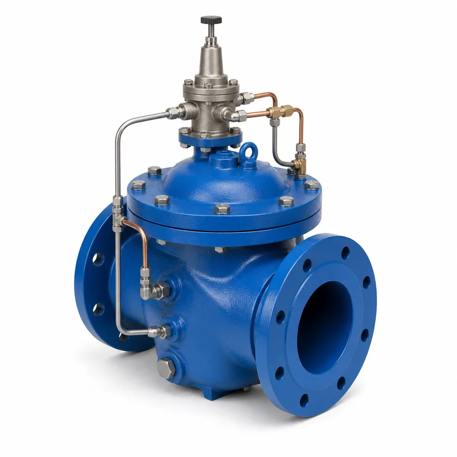
The five hydraulic pilot-operated diaphragm control valves in the TECTUL catalog — Hydraulic Pilot Pressure Reducing Valve, Pressure Sustaining Valve, Water Hammer Anticipator Relief Valve, Float-Pilot Level Control Valve and Solenoid Hydraulic Control Valve — share the same base body: a ductile iron flanged diaphragm valve with a single moving part (the disc-diaphragm assembly), with no external actuator supplying power except the solenoid reference. What changes among the five is the pilot circuit governing that base valve: downstream to reduce, upstream to sustain, the sudden pressure drop to anticipate water hammer, a float's level to fill a tank, or an electrical signal to open and close remotely. This sheet publishes that function matrix, the most common purchasing confusion — reducing versus sustaining, which control opposite sides of the valve —, the anatomy of the pilot circuit (strainer, closing-speed needle valve, isolation cocks), cavitation and reduction ratio, and why correct sizing is by the installation's flow rate, not by pipe diameter.
Important: Before using these data in engineering, design or installation decisions on systems exposed to mechanical, pressure, rupture, fatigue, impact or water-hammer risk, it is essential to read the technical notice and limitation of liability at the end of this sheet.
SKU VT-valvula-reductora-presion-piloto-hidraulica · line of 5 hydraulic pilot-operated diaphragm control valve references, ductile iron body, flanged
1. Technical specifications
Construction common to all five references
| Body and cover | Ductile iron, globe or angle pattern diaphragm valve |
| Diaphragm | Nylon fabric-reinforced rubber (NBR-type elastomer), fully supported by the body and cover: it is the single moving part of the main valve — there are no pistons or sliding stems in the base valve |
| Cast internal components | Ductile iron or CF8M stainless steel (cast equivalent of 316) depending on the part, confirmed per reference with the manufacturer |
| Pilot circuit (common to all five, differing in its control logic — section 2) | Quick-clean Y-strainer, closing speed needle valve (fixed or adjustable orifice), opening speed control, isolation cocks separating the pilot from main line pressure, and the command element proper to each function (reducing pilot, sustaining pilot, pressure-drop trigger, float or solenoid) |
| Flanges | Class 150, per the manufacturer's designation |
| Ends | Flanged |
Regulatory framework and supply conditions
| Valve type | Hydraulic diaphragm control valve, operated by its own pilot circuit, with no external power source (except the electric solenoid reference) |
| Type reference | Family equivalent to hydraulically operated waterworks control valves of the AWWA C530 type; this line's manufacturer does not certify under a specific AWWA number — catalog data, not a standard cited by the product |
| Body material | Ductile iron |
| Flange class | Class 150, as declared by the manufacturer. The usual flange standard for ductile iron bodies is ASME B16.1, which nominally defines class 125 for this material; a class 150 in ductile iron is not the standard's typical construction, and its exact dimensional pattern is confirmed with the reference's factory certificate |
| Ends | Flanged |
| Usual fluids | Potable and treated waterworks water, irrigation and fire protection networks |
| Mounting position | Per the manufacturer's stated orientation; typically horizontal, with the cover and pilot circuit accessible for maintenance |
The five references and their pilot function
| TECTUL reference | Pilot function | Side controlled / event detected |
|---|---|---|
| Hydraulic Pilot Pressure Reducing Valve | Pressure reducing | Constant pressure downstream, regardless of demand variation |
| Pressure Sustaining Valve | Sustaining / relief | Minimum pressure upstream, prioritising high zones of the network before letting flow through to low zones |
| Water Hammer Anticipator Relief Valve | Anticipator | Pressure drop when the pump stops: opens before the return over-pressure wave arrives |
| Float-Pilot Level Control Valve | Level control | Tank level, via a pilot float; automatic filling with no electricity |
| Solenoid Hydraulic Control Valve | Remote open/close | Electrical signal from an external controller, for scheduled irrigation or waterworks |
All five rows use the same diaphragm main valve; what defines the function is the pilot circuit governing that valve's upper chamber (section 2). Dimensions, sizes and maximum admissible pressure per reference are not publicly standardized for this family and are confirmed on quotation with the factory sheet.
⚠ Important: this technical data sheet is a reference guide to the product's properties; it is not a quality certificate for the product you are buying. Heats vary from one another and may differ from the values stated here, or even depart from the standards. If your application requires compliance with a standard, always check the quality certificate (mill certificate) of the lot you are buying. If in doubt, ask one of our technical advisors →
2. The function matrix: one body, five different pilots
The principle: the main valve decides nothing on its own
The diaphragm valve forming the body of all five references is, by itself, a passive closure member: it opens or closes according to the hydraulic pressure it receives in the cover's upper chamber, above the diaphragm. That command pressure is not generated by the main valve, it is set by the pilot circuit — a small assembly of tubing, a pilot (reducing, sustaining or other) and needle cocks, connected between the main line and the cover chamber. Changing the pilot, without touching the main valve, changes the whole function of the assembly. It is the same principle that explains why the catalog carries five separate product sheets for what is, mechanically, the same base valve.
How each pilot governs the main valve
| Function | What the pilot senses | How it acts on the cover chamber | Typical application |
|---|---|---|---|
| Reducing | Downstream pressure | If outlet pressure rises above the setting, the pilot adds pressure to the chamber and closes the main valve; if it falls, it relieves the chamber and opens it | Feeding a low zone of a building or network without exceeding its design pressure |
| Sustaining / relief | Upstream pressure | If inlet pressure falls below the set minimum, the pilot closes the valve to protect that upstream pressure, even if downstream demand exists | Guaranteeing service to high zones of a network before diverting flow to low zones |
| Water hammer anticipator | Sudden pressure drop (pump stop) | The pilot detects the initial drop and opens the main valve immediately, before the return over-pressure wave arrives; it then closes slowly via the closing speed control | Protecting the discharge pipe at the outlet of pumping stations |
| Float-pilot level control | Position of a float inside the tank | The float, mechanically-hydraulically (no electricity), opens or closes the pilot's passage to the cover chamber depending on whether the tank is low or full | Automatic filling of storage tanks where relying on electrical power is undesirable |
| Solenoid | Electrical signal from a controller | A remotely commanded pilot solenoid pressurises or relieves the cover chamber according to the order received | Remote opening and closing of irrigation lines or waterworks sectors from a controller |
This matrix describes the control principle of each function, consistent across multiple hydraulic waterworks control valve manufacturers (Cla-Val, Bermad and equivalents). The exact piping schematic, pilot model and factory settings of each of the five TECTUL references are manufacturer data confirmed on quotation; this sheet does not replace each pilot's installation and adjustment manual.
Why combining functions on the same body is a project decision, not a catalog one
It is technically possible to mount a reducing pilot and a sustaining pilot on the same main valve to obtain a combined function (reduces downstream while also protecting an upstream minimum). The TECTUL catalog publishes the five functions as separate references because that is how they are sold today; a combined-function build on the same body is confirmed with the manufacturer as a special order, not as a catalog reference.
3. Reducing ≠ sustaining: which side each one controls
It is the most common purchasing confusion in this family, because the two valves look almost identical from the outside and both "limit" a pressure: the difference is which side of the valve the pilot governs.
| Hydraulic Pilot Pressure Reducing Valve | Pressure Sustaining Valve | |
|---|---|---|
| Side the pilot senses | Downstream (outlet) | Upstream (inlet) |
| What it keeps constant | Outlet pressure, regardless of how demand varies | A minimum inlet pressure, regardless of how much is demanded downstream |
| Behaviour if the protected pressure falls | Opens further (compensates the outlet drop) | Closes (protects inlet pressure by restricting flow) |
| Selection question | "Do I need the low zone to never receive more pressure than it can withstand?" | "Do I need the high zone of the network not to lose pressure when someone else draws flow?" |
| Symptom of having bought the wrong one | Installed where a sustaining valve was needed: the high zone loses pressure when the low zone's demand starts, because nothing protects the inlet | Installed where a reducing valve was needed: the low zone receives the full inlet pressure with no limit, risking over-pressure in its fittings |
The short selection rule: a reducing valve controls what is after the valve (downstream); a sustaining valve controls what is before it (upstream). Both are mechanically the same main valve — the entire difference is where the pilot's sensing line connects and the open/close logic of that pilot against the pressure it detects.
When a combined function is worthwhile
In networks with high and low zones fed from the same main, it is common to need both functions at once: a sustaining valve protecting the high zone and, downstream of it, a reducing valve limiting the low zone's pressure. These are two separate valves in series, not a single combined catalog reference (section 2).
Where the water hammer anticipator fits in this logic
The anticipator does not sustain or reduce a service pressure: it reacts to an event, the sudden pressure drop following a pump stop, and it gets ahead of the over-pressure wave that follows. It is typically installed on the pumping station's discharge line, not in demand zones, and works alongside — not instead of — the cushioned check valves on the suction and discharge line (the catalog's special check valve data sheet).
4. The pilot circuit, cavitation and sizing by flow rate
Anatomy of the pilot circuit
Regardless of the function, this family's pilot circuit shares the same elements described by function in section 2:
- Quick-clean Y-strainer, upstream of the pilot: protects the pilot's orifice, which is much smaller than the main valve's port and clogs first if the water carries particles.
- Closing speed needle valve, an adjustable orifice that delays the main valve's closure to prevent it from slamming shut and generating its own water hammer — critical on the anticipator, where closure must be deliberately slow after relieving the over-pressure.
- Opening speed control, analogous to the previous one for the opposite direction.
- Pilot isolation cocks, allowing the pilot to be removed or cleaned without dismantling the main valve or interrupting the line.
- The command element proper to the function: reducing or sustaining pilot, pressure-drop trigger, mechanical float or electric solenoid.
Routine maintenance of this family is, in practice, maintenance of the pilot circuit: cleaning the strainer, checking that the needles are not clogged, and verifying the float's free travel or the solenoid's response. The main valve, having no additional moving parts, rarely fails on its own if the pilot is clean and properly adjusted.
Cavitation and reduction ratio
Like any control valve that reduces pressure by throttling the port, this family can cavitate if the ratio between inlet and outlet pressure is excessive for the seat design: the fluid accelerates at the point of maximum restriction, local pressure drops below vapour pressure, and the resulting bubbles collapse downstream, producing a characteristic noise and progressive erosion of the seat and disc. The two-stage split criterion and the reduction-ratio risk threshold are the same as this series' direct-acting line (direct-acting regulators sheet, section 4): ratios on the order of 2:1 to 2.5:1 per stage are low risk; above 4:1 to 6:1 the drop should be split across two piloted valves in series.
Why sizing is by flow rate and not by the line diameter
Installing a piloted valve of the same diameter as the line pipe is this family's most frequent sizing error. The valve must be selected by the installation's real design flow rate at the available pressure drop, not by matching the pipe's nominal diameter: a valve oversized for that flow works with the disc nearly closed most of the time, in the zone where flow is least stable, and that translates into vibration, noise and premature seat wear — whatever function the pilot performs.
5. Frequently asked questions
What is the difference between the reducing valve and the pressure sustaining valve?
The reducing valve controls downstream and the sustaining valve controls upstream. The reducing valve keeps outlet pressure constant against variable demand; the sustaining valve protects a minimum inlet pressure, closing if that inlet pressure falls, regardless of how much is demanded downstream. They are mechanically the same main valve with a different pilot (section 3).
How does the water hammer anticipator work?
It opens before the over-pressure wave arrives. When a pump stops, pressure drops sharply before the return wave generates the destructive over-pressure; the anticipator's pilot detects that initial drop and opens the main valve immediately to divert that wave, then closes slowly thanks to the closing speed control, without generating a second hammer.
Can I fill a tank automatically without electricity?
Yes, with the Float-Pilot Level Control Valve: a float inside the tank governs, mechanically-hydraulically, the pressure in the main valve's cover chamber, opening the passage when the level drops and closing it when it rises — with no reliance on an electrical controller or an electronic level sensor.
Why does my piloted valve vibrate and make noise?
Almost always because of oversizing: if the valve's diameter was matched to the pipe's instead of being calculated from the real design flow rate, the valve works with the disc nearly closed most of the time, in the least stable flow zone, producing vibration and noise; if the reduction ratio is also high, cavitation adds to it (section 4).
What maintenance does this valve family need?
Maintenance is concentrated on the pilot circuit: periodic cleaning of the Y-strainer, checking that the opening and closing speed needles are not clogged, and verifying the float's free travel or the solenoid's response, depending on the reference. The main valve, with a single moving part, rarely needs attention if the pilot is in good condition.
What is the real class of these valves' flanges?
The manufacturer declares class 150 for all five references. The usual flange standard for ductile iron is ASME B16.1 class 125; a class 150 in this material is not that standard's typical construction, so the exact drilling and thickness pattern is confirmed with the factory certificate before coupling to an existing flange.
6. Application notes
Feasibility
The line covers potable and treated waterworks water, irrigation and fire protection networks, across the five hydraulic control functions described: reducing, sustaining, water hammer anticipator, float-pilot level control and solenoid open/close. It is the right choice for waterworks networks, tall buildings and pumping stations requiring stable control at variable flows and large diameters. It is not the choice for small domestic or commercial installations with a single set point, where the threaded direct-acting line (the catalog's direct-acting regulators sheet) is simpler and cheaper to maintain. For critical applications, fire safety or wherever valve failure could compromise a network's service, consult our technical team before specifying.
Installation
Install with a control strainer upstream of the pilot, isolation cocks proper to the pilot circuit (independent of the main line's), and gauges upstream and downstream to verify the actual control point against the factory setting. Confirm the mounting orientation with the manufacturer and leave physical access to the pilot for maintenance without dismantling the main valve. On the water hammer anticipator, verify the closing speed setting in the field with the installation's actual pump, not a generic value. On the level control, verify the float arm's free travel inside the tank.
Design
Select the correct function using the section 3 rule (reducing controls downstream, sustaining controls upstream) before sizing anything. Size by the real design flow rate at the available pressure drop, not by the line pipe's diameter; check the reduction ratio against the section 4 cavitation criterion and split into two stages if it is exceeded. In networks with high and low zones, specify sustaining and reducing as two separate valves in series, not as a combined catalog function. For the anticipator, coordinate the closing speed setting with the project's pumping station water hammer transient analysis.
7. Technical notice and limitation of liability
The body material (ductile iron), the diaphragm (nylon-reinforced rubber) and the declared flange class (150) in this sheet are data TECTUL publishes on each product page, checked against the general documented construction for waterworks-type hydraulic diaphragm control valves (referencing manufacturers such as Cla-Val and Bermad as construction evidence, not as the brand of the TECTUL product). The exact flange class and its dimensional pattern are not certified to a specific standard in this sheet — ASME B16.1 nominally governs class 125 in ductile iron — and are confirmed with the factory certificate before coupling to an existing flange.
The function matrix in section 2 describes the control principle of each function (which side the pilot senses and how it acts on the main valve), consistent across multiple hydraulic waterworks control valve manufacturers. It does not replace the installation, adjustment and maintenance manual for the pilot of each actual reference, supplied by the manufacturer with the product. The cavitation and reduction ratio criteria in section 4 are documented engineering practice, not a limit certified per reference.
These values must not be used as the sole criterion in critical networks, fire protection systems, or wherever valve failure could compromise service to a community, people or property: in such cases hydraulic design, function selection and pilot adjustment belong to the project's responsible engineer, using the network's actual data and the applicable transient analysis. Before deciding with these data, consult our technical team.
Sources
- AWWA C530 (marco de referencia del tipo) — válvulas de control operadas hidráulicamente para redes de agua: familia de reductora, sostenedora, anticipadora, control de nivel y solenoide operadas por un mismo cuerpo de diafragma
- ASME B16.1 — Cast Iron Pipe Flanges and Flanged Fittings: clase nominal 125 para bridas de hierro dúctil/hierro fundido, referencia para contrastar la clase 150 declarada por el fabricante de esta línea
- ASTM A536 — Standard Specification for Ductile Iron Castings: material típico de cuerpo y tapa de las válvulas de control hidráulico de diafragma de este tipo
- Manuales técnicos de fabricantes de válvulas de control hidráulico de diafragma tipo acueducto (Cla-Val, Bermad, y equivalentes): construcción de cuerpo en hierro dúctil, diafragma de caucho reforzado con nylon como único elemento móvil, y anatomía del circuito piloto (filtro, agujas de velocidad de apertura/cierre, llaves de aislamiento) — evidencia de construcción general del tipo, no del fabricante real de las referencias TECTUL
- Bermad — nota técnica sobre válvulas sostenedoras de presión, circulación y alivio en sistemas de riego: distinción de control aguas arriba (sostenedora) frente a aguas abajo (reductora)
- Everfilt — "What Is a Pressure Sustaining Valve?": principio de operación de la válvula sostenedora frente a la reductora
- Bermad / Cougar USA — notas técnicas de cavitación en válvulas de control hidráulico: relación de reducción de riesgo bajo/alto por etapa, criterio compartido con la línea de acción directa de esta serie
- ISA-RP75.23-1995 — índice de cavitación (σ) de referencia: valor mayor a 1,5 indicativo de riesgo bajo-medio
- Fichas de producto TECTUL (tectul.com): Reductora con Piloto Hidráulico, Sostenedora de Presión, Alivio Anticipadora de Golpe de Ariete, Control de Nivel con Flotador Piloto y Control Hidráulica con Solenoide — fuente de material de cuerpo, clase de brida declarada y descripción funcional, agosto 2026
This data sheet is the property of TECTUL, part of the Industrias IMR group. Reproduction without attribution is prohibited. Original document and updates: tectul.com/en/conduccion-de-fluidos/valvulas/ficha-tecnica-valvula-reductora-presion-piloto-hidraulica.html.