 TECTULby IMR
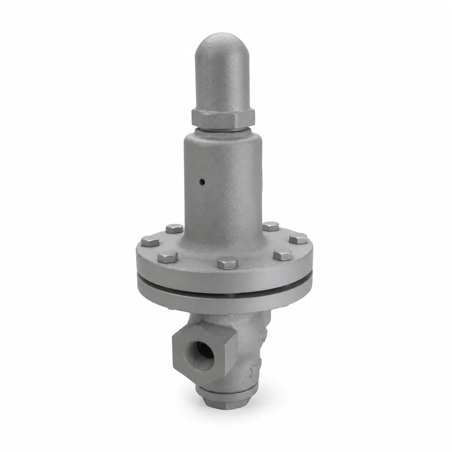
Steam pressure reducing valve, iron body with stainless disc, all-stainless reducing valve, and steam piston valve
TECTUL · Dispatch across Colombia · Exports to Central & South America
Three pressure control references in the TECTUL catalog's steam line: the direct-acting regulator with an iron body and stainless disc, the all-stainless reducing valve for food and pharmaceutical processes where iron is not admissible in contact with the service steam, and the piston valve for steam —shut-off with a ring seal, suited to frequent cycling without stem leakage— as the shutoff valve of the same station. This sheet describes the complete reducing station in the correct order (strainer, separator, trap, reducing valve, downstream safety relief), the difference between direct-acting and pilot-operated designs, the practical limit of single-stage reduction, the phenomenon of regulated pressure falling with flow (droop or fall-off) that no reducing valve fully avoids, and the correct sizing criterion by flow coefficient (Kv/Cv), not by pipe diameter.
Important: Before using these data in engineering, design or installation decisions on systems exposed to mechanical, pressure, rupture, fatigue, impact or water-hammer risk, it is essential to read the technical notice and limitation of liability at the end of this sheet.
SKU VT-valvula-reguladora-vapor-cuerpo-hierro-disco-inox · 3 catalog references: iron/stainless-disc regulator, all-stainless reducer, and steam piston valve
1. Technical specifications
TECTUL catalog references
| Reference | Body | Control element | Typical service |
|---|---|---|---|
| Steam Regulating Valve, Iron Body with Stainless Disc | Cast iron | Stainless steel disc, direct-acting via spring and diaphragm or piston | Pressure reduction in general plant steam lines — heating, industrial processes |
| Stainless Steel Steam Pressure Reducing Valve | Stainless steel | Stainless disc, direct-acting | Food, pharmaceutical, laundry, humidification processes: where iron is not admissible in contact with the service steam |
| Steam Piston Valve | Cast iron | Piston with a compression-set ring seal | Shutoff for the reducing station (upstream and downstream), frequent open-close cycles with no stem leakage |
The catalog lists these three references in sizes from 1/2″ to 2″ depending on variant; the sizes, factory set pressure and Kv/Cv per reference are confirmed on quotation with the factory PDF sheet.
Materials and construction
| Body (iron/stainless-disc regulator) | Cast iron, typically equivalent to ASTM A126 or A48 depending on manufacturer |
| Body (stainless reducer) | Stainless steel, typically a casting equivalent to ASTM A351 CF8/CF8M |
| Actuating element | Calibrated spring + diaphragm or piston, with a manual outlet set adjustment screw under a cap or bonnet |
| Disc/plug | Stainless steel on both regulators, to withstand erosion from high-velocity steam at the seat |
| Piston valve — seal | Compression-set rings on the stem, with no traditional packing gland: reduces stem leakage under frequent cycling |
| Ends | NPT threaded per reference and size |
Regulatory framework and supply conditions
| Device type | Direct-acting pressure regulating/reducing valve (first two references) and piston shutoff valve (third reference) |
| Reference rating | The manufacturer does not publish PMA/TMA nor PMO/TMO for these three references in the current catalog — the same quartet from sheet FT-TC-VAL-TRAMPA-TD-001 applies to these valves' shells and is confirmed on quotation |
| Ends | Female NPT threaded per ASME B1.20.1 |
| Kv/Cv per size | Not published by the manufacturer in the current catalog: an indispensable datum for the sizing in section 4, confirmed on quotation |
| Mounting orientation | Per the flow arrow cast on the body and the manufacturer's marking; many direct-acting regulators require a horizontal position with the spring facing up |
⚠ Important: this technical data sheet is a reference guide to the product's properties; it is not a quality certificate for the product you are buying. Heats vary from one another and may differ from the values stated here, or even depart from the standards. If your application requires compliance with a standard, always check the quality certificate (mill certificate) of the lot you are buying. If in doubt, ask one of our technical advisors →
2. The complete reducing station: order, downstream safety and reduction ratio
The correct order of a reducing station
No steam reducing valve is installed alone in the pipeline: it is part of a train of components whose order is not arbitrary. The standard sequence, from upstream to downstream, is:
- Inlet shutoff valve — to isolate the station for maintenance (this sheet's reference: the steam piston valve, for its tolerance to frequent cycling with no leakage).
- Strainer — retains scale, rust and weld debris before it reaches the reducing valve's seat, the most erosion-sensitive surface in the whole train.
- Moisture separator — removes water carried by wet steam before the reducing valve: liquid water at high velocity erodes the seat and disc far faster than dry steam (section 5).
- Steam trap — discharges the condensate removed by the separator, typically a thermodynamic or inverted bucket trap (sheets FT-TC-VAL-TRAMPA-TD-001 and FT-TC-VAL-TRAMPA-MEC-001) depending on back pressure and service.
- Pressure reducing valve — this sheet's control element, reducing inlet pressure to the outlet pressure required by the process.
- Downstream safety valve — mandatory (see below).
- Outlet shutoff valve — a second piston valve, to isolate the downstream section for maintenance.
Why downstream safety relief is mandatory, not optional
Any pressure reducing valve can fail open —from seat wear, diaphragm or spring failure, or a foreign object trapped under the disc— and in that failure mode it lets the full inlet pressure through to a side of the line designed for the lower outlet pressure. If that downstream side has no safety valve of its own sized for the inlet pressure, the resulting overpressure can exceed the design pressure of the piping, the connected equipment, or downstream instruments. That is why every steam reducing station carries its own downstream safety valve (sheet FT-TC-VAL-SEGURIDAD-001), sized and installed per that family's rules —including the ban on shutoff valves between the protected point and its safety valve— regardless of whether a safety valve already exists on the source boiler.
Maximum single-stage reduction ratio
A single direct-acting reducing valve does not reduce any pressure jump stably or economically. As an order-of-magnitude rule from steam engineering practice, when the ratio of absolute inlet to outlet pressure exceeds roughly 10:1, it is worth splitting the reduction into two stages —two reducing valves in series, each with its own strainer and, where applicable, its own intermediate safety relief— rather than forcing a single valve to work at the edge of its control range. Reducing in two stages also splits the pressure drop and steam velocity between two seats instead of one, which lowers the noise and erosion described in section 5.
The ≈10:1 value is an engineering practice guideline for when evaluating two stages is worthwhile, not a normative limit from a numbered standard. The certified maximum reduction ratio for each TECTUL catalog reference is confirmed on quotation against the manufacturer's curve.
3. Direct-acting vs pilot-operated, and why the set point does not hold exactly (droop/fall-off)
How a direct-acting reducing valve works
In a direct-acting reducing valve —all three references in this sheet are— the outlet pressure acts directly on a diaphragm or piston opposing the set spring. When outlet pressure rises above the set point, it pushes the diaphragm and partially closes the disc, reducing flow; when outlet pressure falls, the spring wins and opens the disc. It is a simple mechanical control loop, with no external power source or electronics, which is why it is the economical solution for most plant stations.
The physical limit of that loop: droop or fall-off
The same mechanism that makes the reducing valve work sets its limit: for the disc to move and modulate flow, the outlet pressure must change a little from the original set point —if it did not change, the diaphragm would have no net force to move the disc—. In practice this means outlet pressure progressively falls as the demanded flow rises, a phenomenon known as droop or fall-off: a reducer set to a given outlet pressure at low or no flow delivers a somewhat lower pressure once flow rises to the top of its range.
- The reducer is set to the desired outlet pressure at low flow (or closed, "no-flow").
- As the process demands more flow, the actual outlet pressure falls below that initial set point, by an amount that grows with flow.
- The correct sizing criterion is to set the reducer accounting for that fall-off at the maximum design flow, not just checking it on the bench at low flow: if the process needs a guaranteed minimum pressure at maximum flow, the no-flow set point must be fixed above that minimum, by exactly enough to cover the expected drop.
- The exact fall-off of each reference —the outlet-pressure-versus-flow curve— depends on the internal design and size, and is not published by the manufacturer in the current catalog: it is confirmed on quotation with the factory PDF sheet.
When a pilot-operated design is justified
A pilot-operated valve adds a second control element —a smaller pilot that senses outlet pressure and repositions the main valve with greater sensitivity— achieving much lower droop and a faster response to large flow swings, at the cost of greater complexity and cost. None of this sheet's three references is pilot-operated: they are direct-acting, suited to services where a moderate outlet-pressure variation between low and maximum flow is acceptable to the process. If the process requires a practically constant outlet pressure across the full flow range —for example, sensitive instrumentation or pharmaceutical processes with a narrow tolerance— a pilot-operated reducer should be evaluated, outside this sheet's scope.
4. Sizing by Kv/Cv, not by pipe diameter
Why pipe diameter is not the criterion
The most frequent error when specifying a steam reducing valve is ordering it "the same size as the pipe." A regulating valve's connection size does not determine its flow capacity: two valves of the same nominal size can have very different flow coefficients (Kv or Cv) depending on the internal seat and disc design. The correct criterion is to calculate the mass flow of steam required by the process at the design outlet pressure, and select the reference and size whose Kv (metric) or Cv (imperial) —published by the manufacturer for each size— covers that flow at the available pressure drop (inlet minus outlet), not simply the size that matches the existing pipe.
Kv and Cv: what they measure
- Cv: flow of water in US gallons per minute passing through the fully open valve with a 1 psi pressure drop.
- Kv: flow of water in cubic meters per hour passing through the fully open valve with a 1 bar pressure drop. Kv ≈ 0.865 × Cv (a common approximate conversion in valve engineering).
- For steam, the admissible mass flow is calculated from the valve's Kv/Cv using the manufacturer's compressible flow formulas (which account for whether the flow is subcritical or critical depending on the pressure ratio), not the simplified liquid-water formula.
The Kv/Cv per size for this sheet's three references is not published by the manufacturer in the current catalog: it is the indispensable datum for correct sizing and is confirmed on quotation with the factory PDF sheet. A reducing valve oversized by pipe diameter —instead of by Kv/Cv— tends to operate near full closure, with the disc far from its optimal control position, which worsens the noise and erosion covered in section 5.
The piston valve as the station's shutoff
This sheet's steam piston valve does not regulate pressure: it is the shutoff element of the station, in the inlet and outlet positions of the train described in section 2. Its compression-set ring seal, instead of a traditional packing gland, is designed for the frequent open-close cycles of maintenance and intervention on a reducing station without developing stem leakage over time — a maintenance advantage over conventional globe or gate valves in the same frequent-cycling service.
5. Noise and erosion from wet steam
Why a reducing valve makes noise
As it reduces pressure, steam accelerates to high velocity through the narrow area left by the partly closed disc, and on large reductions it can reach sonic velocity at the narrowest point (critical flow). That velocity generates turbulence and, under critical flow, shock waves in the vena contracta downstream of the seat: this is the physical source of a reducing station's characteristic noise, which grows with the reduction ratio and the flow rate. New or increasing noise on a reducing valve in service is a sign of seat wear, a reduction ratio that has exceeded a single stage's design range (section 2), or wet steam (see below).
Erosion from high-velocity water droplets
"Dry" steam in industrial practice almost always carries a small fraction of liquid water as fine droplets (wet steam, with a steam quality below 100 %). When that wet steam accelerates through a reducing valve's seat, the water droplets —much denser than steam— impact the disc and seat at high velocity, producing erosive wear (droplet impact erosion) far more aggressive than that of dry steam alone. That accelerated seat wear is the main reason the reducing station includes a moisture separator ahead of the valve (section 2): removing the carried water before it reaches the system's highest-velocity point.
Practical design consequences
- Install the moisture separator and its associated trap always upstream of the reducing valve, never after it.
- Avoid reduction ratios above ≈10:1 in a single stage (section 2): besides affecting droop, they concentrate the entire pressure drop —and all the velocity— on a single seat.
- Size by Kv/Cv (section 4) and not by pipe diameter: an oversized valve operates nearly closed, with the disc exposed to the highest relative flow velocity in that position.
- Plan for acoustic isolation or distance from occupied areas on large reducing stations, where critical-flow noise can exceed comfort or hearing-safety levels, a datum for the project's acoustic or process engineer.
6. Frequently asked questions
Why doesn't my steam reducing valve hold the exact outlet pressure?
It is a physical phenomenon called droop or fall-off: outlet pressure progressively falls as flow rises, because the direct-acting mechanism needs the outlet pressure to change slightly to move the disc. It is not a valve fault. Details and the setting criterion are in section 3.
What order do a reducing station's components go in?
Inlet shutoff valve, strainer, moisture separator, steam trap, the reducing valve, the downstream safety valve and the outlet shutoff valve, in that order. Each component protects the next. The full sequence is in section 2.
Is a safety valve after the reducing valve mandatory?
Yes. A reducing valve can fail open and let the full inlet pressure through to a side of the line designed for a lower pressure. The downstream safety valve protects against that scenario and is independent of any safety valve that may already exist on the source boiler. Details are in section 2.
How is a steam reducing valve correctly sized?
By the valve's Kv or Cv flow coefficient against the required steam mass flow and the available pressure drop, not by the connecting pipe diameter. A valve oversized by diameter operates nearly closed and is noisier and wears faster. The development is in section 4.
When is it worth splitting the reduction into two stages?
When the ratio of absolute inlet to outlet pressure exceeds roughly 10:1. Splitting into two stages divides the pressure drop between two seats, reduces noise and erosion, and makes a more manageable droop easier to hold at each stage. Details are in section 2.
Why is a moisture separator needed before the reducing valve?
Because wet steam carries water droplets that, once accelerated through the reducing valve's seat, erode the disc and seat far faster than dry steam. The separator removes that water before it reaches the system's highest-velocity point. Details are in section 5.
7. Application notes
Feasibility
The iron/stainless-disc regulator covers pressure reduction in general plant steam; the stainless reducer covers food and pharmaceutical processes where iron is not admissible in contact with steam; the piston valve covers the station's shutoff with tolerance to frequent cycling. None of the three includes, in this sheet, the Kv/Cv per size, the PMA/TMA/PMO/TMO rating, nor the fall-off curve: these are confirmed on quotation with the factory PDF sheet. It is not the choice when the process requires a practically constant outlet pressure across the full flow range (a pilot-operated design is needed, out of scope) nor when the reduction ratio exceeds ≈10:1 in a single undivided stage (section 2). For critical or safety applications, consult our technical team before specifying.
Installation
Install in the station's complete order: inlet shutoff, strainer, moisture separator, trap, reducing valve, downstream safety relief and outlet shutoff (section 2). Verify the mounting orientation against the manufacturer's marking —many direct-acting reducers require a horizontal position with the spring facing up—. Do not omit the moisture separator or the downstream safety relief under any circumstance: they are part of the train's protection, not optional accessories. Leave access to the set adjustment screw under its cap or bonnet.
Design
Size by Kv/Cv against the required steam mass flow and the available pressure drop, not by pipe diameter (section 4). Check the reduction ratio against the ≈10:1 per-stage guideline and evaluate two stages if it is exceeded (section 2). Set the no-flow set point accounting for the fall-off expected at maximum design flow, to guarantee the minimum pressure the process needs (section 3). Always include the downstream safety valve sized for the inlet pressure, with its own installation rules from sheet FT-TC-VAL-SEGURIDAD-001, and the moisture separator if the supply steam is not dry.
8. Technical notice and limitation of liability
This sheet describes the engineering framework of steam reducing stations (component order, downstream safety, direct action and fall-off, Kv/Cv sizing) combined with the data TECTUL publishes on each product's page (service, body material). None of the three references in this sheet includes Kv/Cv per size, a fall-off curve, PMA/TMA/PMO/TMO, nor a certified reduction ratio: those data are confirmed on quotation with the factory PDF sheet of the actual reference.
The ≈10:1 maximum single-stage reduction ratio guideline (section 2) and the noise and erosion analysis (section 5) are generalized principles of steam engineering practice, backed by compressible flow physics and the known behavior of wet steam, not figures from a numbered standard table. The exact values for each TECTUL catalog reference are confirmed on quotation.
This family protects equipment and processes where downstream overpressure from a reducing-valve failure can compromise piping, connected equipment or personnel safety: these values must not be used as the sole criterion for the station's design. Sizing the complete train, including the downstream safety valve, always belongs to the project's responsible engineer under the applicable code. Before deciding with these data, consult our technical team.
Sources
- ASME Boiler and Pressure Vessel Code, Section VIII, Division 1 — marco de referencia de la válvula de seguridad aguas abajo obligatoria de la sección 2, desarrollada en la ficha FT-TC-VAL-SEGURIDAD-001
- ASTM A126 — Standard Specification for Gray Iron Castings for Valves, Flanges, and Pipe Fittings: designación típica del cuerpo de hierro de la reguladora con disco inoxidable
- ASTM A351/A351M — Standard Specification for Castings, Austenitic, for Pressure-Containing Parts: grado CF8/CF8M típico del cuerpo de la reductora inoxidable
- ASME B1.20.1 — Pipe Threads, General Purpose, Inch: rosca NPT de las conexiones
- Principios de flujo compresible en válvulas de control — definición y cálculo de Kv/Cv y régimen subcrítico/crítico, base del criterio de dimensionamiento de la sección 4
- NIST/ASME Steam Tables — propiedades termodinámicas del vapor húmedo y título de vapor, base física de la erosión por gotas de agua de la sección 5
- ISO 6552 — Automatic steam traps — Marking (PMA, TMA, PMO, TMO): mismo marco de lectura aplicado a la carcasa de las válvulas reductoras y reguladoras de esta ficha
- Fichas de producto TECTUL (tectul.com): Válvula Reguladora de Vapor Cuerpo de Hierro Disco Inox, Válvula Reductora de Presión de Vapor Inoxidable, y Válvula de Pistón Para Vapor — fuente primaria de servicio, material y descripción por referencia
- Curaduría interna TECTUL (data/etapas/etapa-1-conduccion-de-fluidos/curaduria.json) — referencias, agosto 2026
This data sheet is the property of TECTUL, part of the Industrias IMR group. Reproduction without attribution is prohibited. Original document and updates: tectul.com/en/conduccion-de-fluidos/valvulas/ficha-tecnica-valvula-reguladora-vapor-cuerpo-hierro-disco-inox.html.