 TECTULby IMR
Spring-loaded safety and relief valves, bronze body (boilers, water heaters, air, kettles) and stainless steel relief
TECTUL · Dispatch across Colombia · Exports to Central & South America
Spring-loaded, cast bronze body safety valves from the TECTUL catalog —for boilers, water heaters, compressed air and kettles— and a stainless steel relief valve for corrosive or sanitary fluids. This is the family that most demands vocabulary precision: a safety valve (sudden opening, for gas or compressible steam) and a relief valve (proportional opening, for incompressible liquid) are not synonyms even though commercial catalogs use them interchangeably, and the code framework governing them —ASME Section I for boilers, Section VIII for pressure vessels— sets different requirements for overpressure, blowdown and testing. This sheet fixes that vocabulary, summarizes both code frameworks, and documents the trade's most basic safety rule: never a shutoff valve between the protected equipment and the safety valve, nor on its discharge.
Important: Before using these data in engineering, design or installation decisions on systems exposed to mechanical, pressure, rupture, fatigue, impact or water-hammer risk, it is essential to read the technical notice and limitation of liability at the end of this sheet.
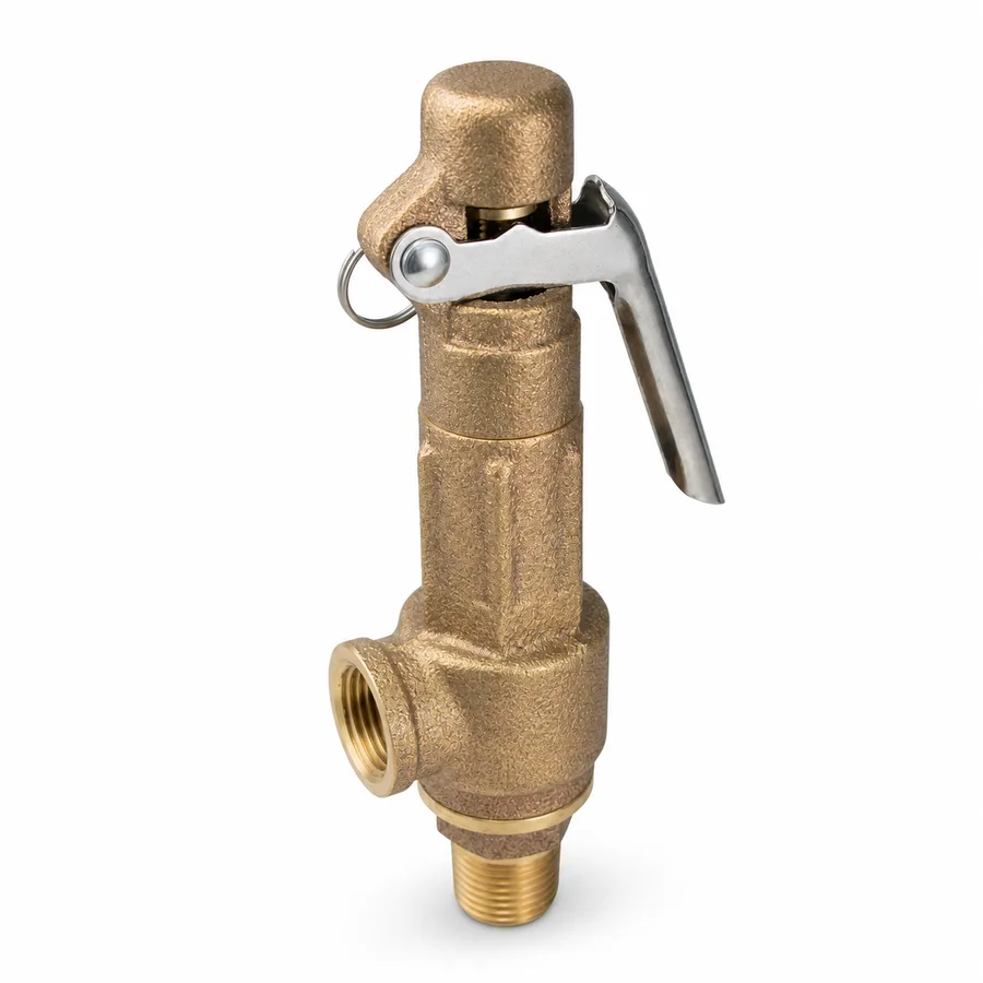
SKU VT-86911 (bronze boiler safety valve) · 5 catalog references: boilers, water heater, air, kettle (bronze) and relief (stainless steel)
1. Technical specifications
TECTUL catalog references by service and material
| Reference | Body | Service | Sizes / ranges offered |
|---|---|---|---|
| Bronze Safety Valve for Boilers | Cast bronze | Steam boilers, hot water, natural gas | 1/2″ · 3/4″ · 1″ · 1-1/4″ · 1-1/2″; factory set ranges 50 / 75 / 100 / 125 / 150 lb |
| Bronze Safety Valve for Water Heaters | Cast bronze | Water heaters, steam, air or gases | 1/2″; factory set range confirmed on quotation |
| Bronze Safety Valve for Compressed Air | Cast bronze | Compressed air systems | 1/4″ and 1/2″; includes a 30 psi set variant among others |
| Safety Valve for Kettles | Cast bronze | Kettles and pressurized steam or gas vessels | 3/4″; includes a 0-10 psi set variant among others |
| Stainless Steel Relief Valve | Stainless steel | Corrosive or sanitary process fluids, where bronze is not admissible | Sizes and set range confirmed on quotation |
IMPORTANT
This data sheet is a reference guide to the properties of this product type. The measurements, dimensions and physical or geometric characteristics of the product actually supplied may vary by manufacturer and lot, and may even fall outside the cited standards. If any of these figures is critical to your design or build, it is essential to verify it with one of our advisors against the physical product, so you can be fully certain of what you are buying. · Original data sheet: tectul.com/en/conduccion-de-fluidos/valvulas/ficha-tecnica-valvula-seguridad-bronce-para-calderas.html
The manufacturer does not publish the full list of set ranges nor face-to-face dimensions per size for every reference in the current catalog: the exact ranges per variant and size are confirmed on quotation with the factory PDF sheet.
Materials and construction
| Body (bronze references) | Cast bronze, typically equivalent to ASTM B62 (general-purpose copper-tin-zinc-lead valve alloy) |
| Body (stainless reference) | Austenitic stainless steel, typically a casting equivalent to ASTM A351 grade CF8/CF8M |
| Spring | Spring steel factory-calibrated to the reference's set pressure; not user-adjustable without breaking the factory seal |
| Disc / seat | Metal-to-metal or with an elastomeric insert depending on reference and service, factory data |
| Test lever | Manual lever to lift the disc off the seat and verify it is not stuck or obstructed, without needing to reach set pressure |
| Factory seal | Seal over the spring adjustment: breaking it voids the set warranty and requires recalibration on a certified bench |
| Ends | NPT threaded per reference (inlet and outlet) |
Regulatory framework and supply conditions
| Device type | Sudden-opening spring safety valve (boilers, water heater, air, kettle) or proportional-opening relief valve (stainless reference) — see the exact vocabulary in section 2 |
| Code framework | ASME Section I (steam-generating equipment: boilers) or Section VIII (pressure vessels: water heaters, kettles, air tanks), depending on the protected equipment — see section 3 |
| Set pressure | Factory-fixed by the manufacturer for each reference and variant; the exact range per size is confirmed on quotation |
| Ends | NPT threaded per ASME B1.20.1 |
| Discharge | Must be piped to a safe location with no additional restrictions — see section 5 |
⚠ Important: this technical data sheet is a reference guide to the product's properties; it is not a quality certificate for the product you are buying. Heats vary from one another and may differ from the values stated here, or even depart from the standards. If your application requires compliance with a standard, always check the quality certificate (mill certificate) of the lot you are buying. If in doubt, ask one of our technical advisors →
2. The correct vocabulary: safety valve, relief valve, set and overpressure
The commercial catalog in Spanish uses "safety valve" and "relief valve" interchangeably, but code vocabulary in English —the language ASME I and VIII are written in— distinguishes two devices by their opening mode, not by their commercial name:
| Term | Opening mode | Typical fluid | Example in this sheet |
|---|---|---|---|
| Safety valve | Sudden: on reaching set pressure, the disc pops fully open ("pop") due to the rapid expansion of a compressible fluid behind it | Gas or steam (compressible) | Boilers, water heater, kettle: all handle steam or gas |
| Relief valve | Proportional: the disc opens gradually, in proportion to the pressure excess over set, because an incompressible liquid does not produce the sudden-expansion effect | Liquid (incompressible) | Water or process liquid applications |
| Safety relief valve | Dual: designed to pop open in gas/steam and open proportionally in liquid, depending on the actual installed service | Gas/steam or liquid, per certification | Typical use on vessels that may hold either fluid under different conditions |
This sheet's compressed air reference handles a compressible gas: strictly in vocabulary terms, it is a safety valve. The stainless reference, aimed at process fluids, may correspond to a relief valve service depending on the project's actual fluid —liquid or gas—, a datum that should be verified against that reference's factory sheet.
Set pressure, overpressure and blowdown: three figures, not one
- Set pressure: the pressure at which the disc begins to lift, factory-fixed and sealed.
- Overpressure (accumulation): the margin above set that the code allows before the valve delivers its certified full-discharge capacity. It is not a defect: it is part of the code's design, which recognizes that no valve opens to full capacity exactly at the instant of set.
- Blowdown (reseat differential): the pressure drop, below the set pressure, at which the valve reseats and closes after relieving the overpressure. Insufficient blowdown causes the valve to open and close in rapid cycles ("chatter") that wear it out; excessive blowdown wastes more fluid than necessary on each event.
The exact overpressure and blowdown percentages allowed depend on the applicable code (ASME I or VIII) and on the installation type (a single valve or multiple valves on the same equipment) — developed in section 3. None of this sheet's five references certifies its discharge capacity (kg/h or SCFM) in the current catalog: that datum, together with the factory overpressure and blowdown percentages, is confirmed on quotation.
3. ASME Section I versus Section VIII: what each code requires
The ASME Boiler and Pressure Vessel Code splits overpressure protection into two distinct sections, depending on what is being protected, and that distinction decides which valve and which test apply to each reference in this sheet.
| Criterion | ASME Section I — Power Boilers | ASME Section VIII — Pressure Vessels (Division 1) |
|---|---|---|
| What it protects | Steam-generating boilers: the drum, the superheater and the water-steam circuits | Pressure vessels that do not generate steam by direct combustion: water heaters, air tanks, kettles, heat exchangers |
| References in this sheet | Bronze Safety Valve for Boilers | Water heater, compressed air, kettle and (depending on the project's fluid) the stainless relief valve |
| Code terminology | "Safety valve" — sudden opening is assumed because the fluid is always steam | "Safety valve," "relief valve" or "safety relief valve" depending on the actual fluid (section 2) |
| Relieving capacity | Must cover the boiler's maximum steam generation at design pressure, certified by the valve manufacturer | Must cover the vessel's governing overpressure case (blocked outlet, external fire exposure or other applicable scenario), certified by the manufacturer |
| Manual test lever | Required by the code to verify in operation that the disc is not stuck | Required where the fluid's service and temperature allow it (hot water, steam); not always applicable in cold process liquid service |
Overpressure and blowdown: the general pattern of both codes
Both ASME code sections recognize that a safety valve does not deliver its certified discharge capacity exactly at set pressure, but with an overpressure (accumulation) margin above that point, and that on relieving the overpressure the valve does not close exactly at set pressure but somewhat below it, through blowdown (section 2). The exact overpressure and blowdown percentages allowed —which vary depending on whether it is a single valve or multiple valves on the same equipment, and on the service type— are set by each applicable code's current edition (ASME Section I or Section VIII) and are not reproduced per reference in this sheet: they are a design datum that must be verified against the project's current code edition, not a generic catalog number.
None of this sheet's five references is certified here under a specific ASME manufacturing code stamp nor under the National Board "UV" or "UM" seal: the manufacturing certificate, the code edition under which each reference was built and tested, and the exact factory overpressure and blowdown percentages are confirmed on quotation. For equipment subject to regulatory inspection (boilers and pressure vessels under local authority or insurer jurisdiction), selecting the certified valve is the responsibility of the project's responsible engineer.
4. The code rule: never a shutoff valve upstream nor on the discharge
The trade's most basic rule
It is the most basic —and most frequently violated in the field— safety rule in the entire valve line: a shutoff valve is never installed between the protected equipment and the safety valve, nor on its discharge line, except in very specific certified interlocked code arrangements (for example, a three-way changeover valve between two redundant safety valves, designed so that at least one is always in service) that do not apply to this sheet's references.
The reason is direct: a shutoff valve closed upstream of the safety valve —by mistake, by maintenance not returned to position, or by unauthorized tampering— leaves the protected equipment with no pressure relief at all, exactly the condition the valve exists to prevent. A shutoff valve closed on the discharge has the same effect through another path: even if the safety valve opens correctly, the fluid has nowhere to go and pressure builds up all the same, with the added risk of overpressuring the safety valve's own body on its discharge side, which is not designed to contain pressure there.
Practical consequence: isolate the equipment, not the valve
When equipment with a safety valve requires maintenance intervention, the correct procedure is to isolate and depressurize the equipment (boiler, heater, air tank, kettle), not to place a valve between it and its safety valve to "make the work easier." If the design requires being able to swap the safety valve without taking the equipment out of service, a certified interlocked redundant-valve arrangement is called for —not a simple shutoff— and that decision belongs to the project's responsible engineer under the applicable code.
Field verification
- Visually confirm, before starting up any equipment with a safety valve, that no manual valve exists between the equipment and the safety valve nor on its discharge.
- If a shutoff valve is found in either of those two positions, report it as a safety nonconformity before operating the equipment, without exception.
- The factory seal over the spring adjustment (section 1) is also a field check: a broken seal with no record of certified recalibration is a nonconformity.
5. Piped discharge, back pressure and testing frequency
Piped discharge to a safe location
The discharge of a steam or hot-gas safety valve must not be directed anywhere it could injure a person or damage nearby equipment: the code requires piping it, without reducing the valve's outlet diameter, to a safe point (outdoors, to a vent tank, or to drainage depending on the fluid). The discharge piping must be independently supported, so that its weight and the reaction of the escaping jet do not load the valve body or twist its seat.
The effect of accumulated back pressure on the set point
If the discharge piping is long, has many elbows, or discharges into a common header with other valves, a back pressure builds up on the valve's outlet side during the relief event. That back pressure acts against the spring and, depending on the valve's design, can: (a) effectively add to the set pressure, delaying opening; or (b) in balanced-bellows valves, be compensated so it does not affect the set point. Back pressure not accounted for in the discharge line's design can make the valve open late, close unstably, or fail to deliver its certified capacity — the same kind of design error as incorrect upstream piping sizing in other valve families, transposed here to the discharge side.
Manual test lever: what it verifies and what it does not
The test lever allows the disc to be lifted by hand to confirm it is not stuck to the seat from corrosion, deposits or disuse, without pressurizing the system up to set pressure. It is a mechanical check that the disc moves freely, not a test that the set pressure is correct nor that the spring retains its calibration: that verification requires a pressure test on a certified bench or, under some codes and equipment, a supervised in-place test at real pressure.
Testing frequency
How often the test lever must be operated and the valve recalibrated or replaced depends on the applicable code, the equipment type, the inspection jurisdiction (local authority or insurer) and the service history: it is not a single, universal interval for this sheet's five references. Setting that frequency against the applicable code and jurisdiction is the responsibility of the project's responsible engineer or the protected equipment's regulatory inspection program.
6. Frequently asked questions
What is the difference between a safety valve and a relief valve?
A safety valve opens suddenly and fully on reaching its set pressure, and is used on gas or steam. A relief valve opens gradually, proportional to the pressure excess, and is used on liquid. The difference is set by the fluid's compressibility, not by the commercial name. Details are in section 2.
Can a shutoff valve be installed upstream of a boiler's safety valve?
No, never, except for a certified interlocked redundant-valve arrangement designed for that purpose. It is the most basic code rule in the whole family, and violating it leaves the equipment without effective overpressure protection. Details are in section 4.
What about on the discharge?
Not there either. A shutoff valve on the discharge prevents the relieved fluid from having anywhere to go, and pressure builds up just as if the safety valve did not exist, with the added risk of overpressuring the valve's own outlet side. Section 4.
Which code governs my boiler, and which my water heater or kettle?
Steam-generating boilers are governed by ASME Section I; pressure vessels that do not generate steam by direct combustion —water heaters, air tanks, kettles— by ASME Section VIII. Each code sets its own overpressure, blowdown and testing framework. The comparative summary is in section 3.
How often is a safety valve tested?
It depends on the applicable code, the equipment type and the inspection jurisdiction (local authority or insurer): there is no single interval for this sheet's five references. The manual test lever verifies the disc is not stuck, but does not replace the certified-bench pressure test that confirms the set pressure. Setting the exact frequency is the responsibility of the project's responsible engineer.
Why does my safety valve open and close several times in a row (chatter)?
Almost always because of insufficient blowdown for the installation, or unforeseen discharge back pressure in the outlet piping design, which destabilizes the reseat point. Details are in sections 2 and 5.
7. Application notes
Feasibility
The bronze references cover protection of steam and hot water boilers, water heaters, compressed air and kettles under ASME Section I or VIII depending on the equipment (section 3); the stainless reference covers corrosive or sanitary fluid service where bronze is not admissible. None of the five references in this sheet includes the certified discharge capacity (kg/h or SCFM), the exact factory overpressure and blowdown percentages, nor the manufacturing code stamp (UV/UM): these are confirmed on quotation with the certificate and factory PDF sheet. This family protects equipment whose failure endangers people and property: for any final selection, consult our technical team and verify the code and inspection jurisdiction applicable to the project.
Installation
Install directly on the protected equipment, in a vertical position per the manufacturer's marking, with no shutoff valve between the equipment and the safety valve nor on its discharge (section 4, no exceptions except a certified redundancy arrangement). Route the discharge through unreduced-diameter piping to a safe location, with that piping independently supported so it does not load the valve body (section 5). Verify the factory seal is intact before commissioning, and do not break it or attempt to readjust the spring in the field.
Design
First determine the applicable code framework —ASME Section I for boilers, Section VIII for the rest— and with it the required relieving capacity, overpressure percentage and blowdown for the equipment's governing scenario (section 3), data requested by the project's responsible engineer against the code's current edition. Verify the safety/relief vocabulary against the actual fluid's compressibility before specifying (section 2), and design the discharge piping accounting for the back pressure it can generate at the set point (section 5). Set the testing and recalibration frequency against the applicable inspection jurisdiction, not against a generic catalog interval.
8. Technical notice and limitation of liability
This sheet describes the code framework and normative vocabulary of safety and relief valves (ASME Boiler and Pressure Vessel Code, Sections I and VIII), combined with the data TECTUL publishes on each product's page (service, sizes and declared set ranges). None of the five references in this sheet includes certified discharge capacity, exact factory overpressure or blowdown percentage, nor a manufacturing code stamp (UV/UM): those data are confirmed on quotation with the certificate and factory PDF sheet of the actual reference.
The safety valve / relief valve vocabulary and the ASME Section I vs. Section VIII comparative summary in sections 2 and 3 are a general reading framework for the code, not a certification that any reference in this sheet meets a specific ASME I or VIII edition for a given piece of equipment: that certification depends on the actual manufacturer, the stamp obtained and the code edition current on the project, and is verified with the factory certificate.
This family protects equipment whose failure can endanger people, property and the environment: these values must not be used as the sole criterion for selection, installation or maintenance under any circumstance. Selecting the certified valve, sizing its relieving capacity, setting the testing frequency and complying with the applicable code and inspection jurisdiction always belong to the project's responsible engineer. Before deciding with these data, consult our technical team.
Sources
- ASME Boiler and Pressure Vessel Code, Section I — Rules for Construction of Power Boilers: marco de código para válvulas de seguridad de calderas generadoras de vapor
- ASME Boiler and Pressure Vessel Code, Section VIII, Division 1 — Rules for Construction of Pressure Vessels: marco de código para válvulas de seguridad y alivio de recipientes a presión (calentadores, tanques de aire, marmitas)
- API Recommended Practice 520 — Sizing, Selection, and Installation of Pressure-relieving Devices: criterios generales de dimensionamiento, selección e instalación de válvulas de seguridad y alivio
- API Recommended Practice 521 / ISO 23251 — Pressure-relieving and Depressuring Systems: guía de diseño de sistemas de descarga, incluida la consideración de contrapresión acumulada
- ASTM B62 — Standard Specification for Composition Bronze or Ounce Metal Castings: aleación de bronce típica del cuerpo de las cuatro referencias de esta línea
- ASTM A351/A351M — Standard Specification for Castings, Austenitic, for Pressure-Containing Parts: grado CF8/CF8M típico del cuerpo de la referencia de alivio inoxidable
- ASME B1.20.1 — Pipe Threads, General Purpose, Inch: rosca NPT de las conexiones
- Fichas de producto TECTUL (tectul.com): Válvula de Seguridad Bronce Para Calderas, Para Calentador, Para Aire Bronce, Para Marmita, y Válvula de Alivio Inoxidable — fuente primaria de servicio, diámetros y rangos de ajuste declarados
- Curaduría interna TECTUL (data/etapas/etapa-1-conduccion-de-fluidos/curaduria.json) — diámetros por referencia, agosto 2026
This data sheet is the property of TECTUL, part of the Industrias IMR group. Reproduction without attribution is prohibited. Original document and updates: tectul.com/en/conduccion-de-fluidos/valvulas/ficha-tecnica-valvula-seguridad-bronce-para-calderas.html.