
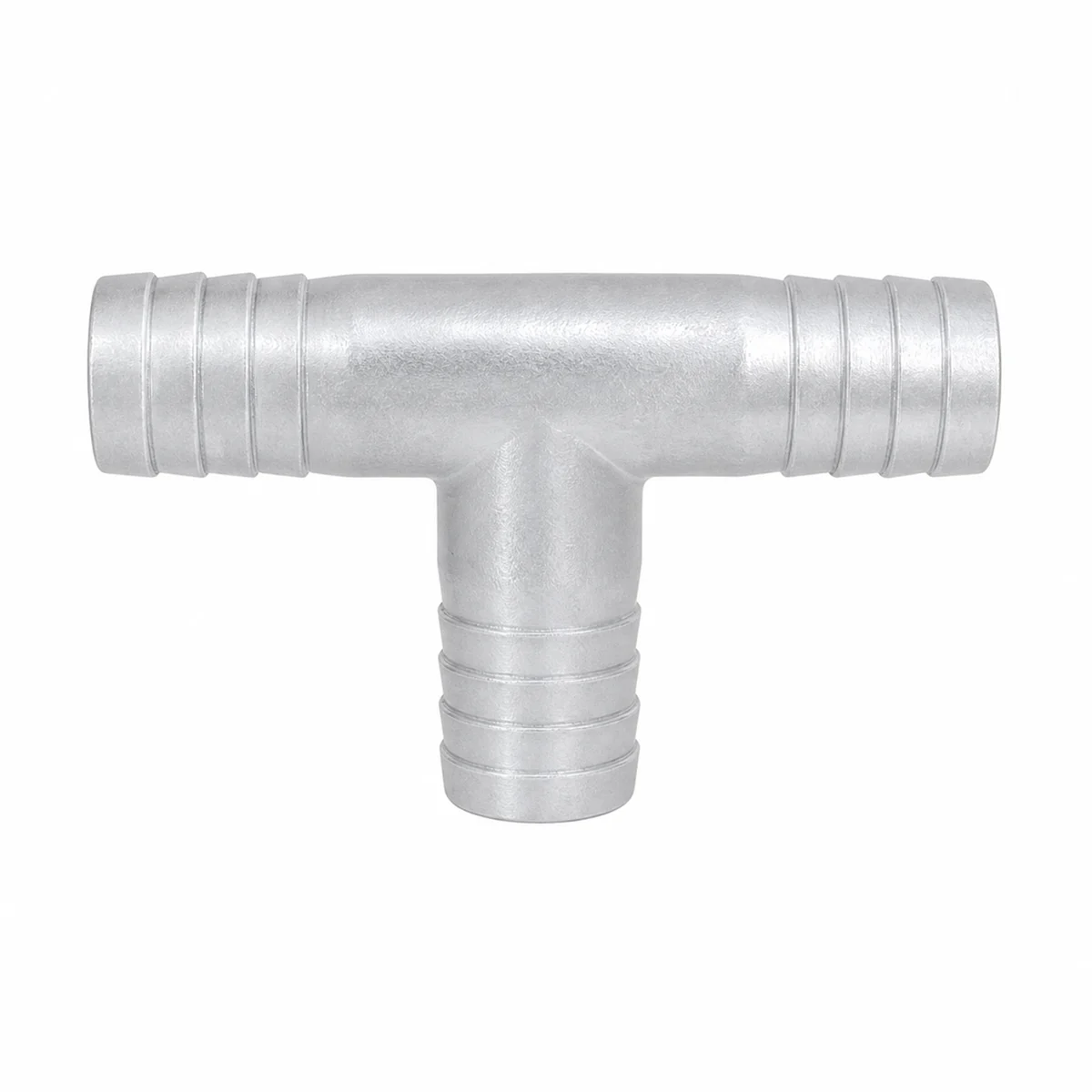
Aluminum hose barbs and tees — reducing male, hose tee, female tee and reducing union
TECTUL · Dispatch across Colombia · Exports to Central & South America
Family of aluminum fittings for water-transfer, fuel and aluminum-compatible fluid hose, distinct from the camlock system in the same line (see the FT-TC-RAC-CAMLOCK-ALUMINIO-001 sheet): these parts use a smooth barbed spigot, retained with a DIN 3017 worm-drive clamp behind the spigot's raised bead, and/or NPT thread. Includes the three-port hose tee (1/2″–4″), the reducing female-threaded tee, the reducing male NPT x hose adapter, and the reducing union to splice two different hose diameters.
Important: Before using these data in engineering, design or installation decisions on systems exposed to mechanical, pressure, rupture, fatigue, impact or water-hammer risk, it is essential to read the technical notice and limitation of liability at the end of this sheet.
Hose tee (VT-58618) · female tee (VT-58619) · reducing male (VT-58636) · reducing union (VT-58638) · sold by the unit
1. Technical specifications
| Hose tee (VT-58618) | Three barbed ports of the same diameter, 1/2″ to 4″; secured with a DIN 3017 worm-drive clamp behind the spigot's retention bead |
| Reducing female tee (VT-58619) | Female NPT threaded straight run, smaller-diameter branch; combinations from 1″x1/2″ |
| Reducing male (VT-58636) | Male NPT thread on one end, smaller-diameter barbed spigot on the other; combinations from 3/4″ NPT |
| Reducing union (VT-58638) | Two barbed spigots of different diameter, to splice hoses of different sizes |
| Material (all) | Aluminum |
| Barbed-end retention | DIN 3017 worm-drive clamp, installed behind the spigot's retention bead |
| Thread (where applicable) | NPT per ANSI/ASME B1.20.1 |
Exact dimensions per combination (diameters, lengths, weight): the available manufacturer tables have cells that cannot be unambiguously attributed to each combination due to an alignment issue in the source document; they are confirmed on quotation rather than assigned by position.
2. Frequently asked questions
Are these parts part of the camlock system in the same line?
No. They are a separate family of barbed spigot + DIN 3017 clamp and/or NPT thread, without the camlock lug mechanism. For aluminum camlock see the FT-TC-RAC-CAMLOCK-ALUMINIO-001 sheet.
What clamp do I need?
A worm-drive clamp conforming to DIN 3017, sized to the hose's actual outer diameter, installed behind the spigot's bead to prevent it from slipping under pressure.
3. Application notes
Feasibility
Suitable for water, fuel and aluminum-compatible fluid transfer via flexible hose. Do not specify without first confirming the exact dimensions of the required combination with the supplier.
Installation
Insert the hose fully onto the barb and secure with a DIN 3017 clamp behind the retention bead. Seal NPT threads with PTFE tape or a compatible sealant before threading.
Design
Confirm the exact dimensions of the required combination with the supplier before detailing installation drawings. Verify the aluminum's chemical compatibility with the service fluid.
4. Technical notice and limitation of liability
The pressures, dimensions, weights and other characteristics in this sheet are theoretical calculation values obtained from nominal properties published in the standards cited (ASME B36.10-2022, ASME B31.3-2024, ASTM A106/A106M-19a, ASTM A53/A53M-24, API Spec 5L 46th ed.). They guide selection; they are not a certificate of conformity for any given lot.
The actual behavior of each lot varies with manufacturing — wall tolerance (up to −12.5%), out-of-roundness, residual stresses — and with the raw material — chemical composition within the ranges the standard allows, heat-to-heat differences. To certify a lot, the tests defined by its product standard are required: tensile test, flattening test and hydrostatic test, documented in the manufacturer's mill test certificate (MTC), which TECTUL supplies upon request; testing of the lot in an independent laboratory can also be arranged.
These values must not be used as the sole criterion in critical or safety applications, or wherever failure of the line may compromise people, property or the environment: in such cases the design belongs to the project's responsible engineer under the applicable code (ASME B31.3, B31.1 or the one governing the installation), with the design temperature, corrosion allowance and load cases of the actual service. Before deciding with these data, consult our technical team.
Sources
- ANSI/ASME B1.20.1-2013 (R2018) — Pipe Threads, General Purpose, Inch (rosca NPT)
- DIN 3017 — Hose clips (worm-drive, screw-type) (abrazadera de fijación en extremos de espigo)
- Páginas de producto TECTUL "Tee Manguera Aluminio" (VT-58618), "Tee Hembra Aluminio Roscada" (VT-58619), "Macho Reducido Aluminio NPT para Manguera" (VT-58636) y "Unión Reducida Aluminio" (VT-58638), previews/conduccion-de-fluidos/racores-y-acoples/: rango de diámetros, montaje DIN 3017 y función de cada pieza
- Fichas de fabricante "Tee Manguera Aluminio", "Tee Hembra Manguera Aluminio", "Macho Reducido Aluminio" y "Unión Reducida Aluminio" (catálogo de accesorios de manguera en aluminio, IMR/TECTUL): confirman rango de tallas; tabla dimensional detallada con desalineación de columnas no utilizable de forma inequívoca
This data sheet is the property of TECTUL, part of the Industrias IMR group. Reproduction without attribution is prohibited. Original document and updates: tectul.com/en/conduccion-de-fluidos/racores-y-acoples/ficha-tecnica-tee-manguera-aluminio.