 TECTULby IMR
Metallic-body air valves per AWWA C512 — flanged triple-action, bronze purger and nickel-plated brass purger
TECTUL · Dispatch across Colombia · Exports to Central & South America
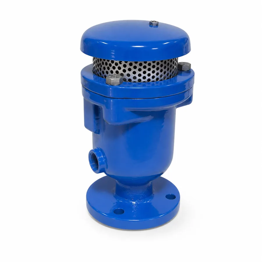
TECTUL's line of metallic-body air valves, standardized under AWWA C512: the flanged metallic triple-action air valve, in ductile iron, which expels large volumes of air when filling the line, admits air when draining it and purges the air that accumulates during pressurized operation; and two threaded purgers with a small orifice — bronze and nickel-plated brass — that perform only the third function, automatic release of dissolved air during normal service. This sheet maps the three air functions in a pressurized line to the three references, publishes the orifice diameter and its effect on venting flow, the AWWA C512 working and test pressure, and the criteria for locating the correct air valve along the pipeline profile.
Important: Before using these data in engineering, design or installation decisions on systems exposed to mechanical, pressure, rupture, fatigue, impact or water-hammer risk, it is essential to read the technical notice and limitation of liability at the end of this sheet.
SKU VT-ventosa-triple-accion-metalica-bridada · line of 3 references: flanged triple-action, bronze purger and nickel-plated brass purger
1. Technical specifications
The three TECTUL catalog references
| Reference | Material | End | Catalog sizes | Function |
|---|---|---|---|---|
| Flanged Metallic Triple-Action Air Valve | Ductile iron (body and cover) | Flanged | Made to order — the AWWA C512 type covers 1/2" to 20" (13–500 mm); the lot's flange pattern and class are confirmed on quotation | Combination (triple action): large-flow air/vacuum on filling and draining + automatic release during operation |
| Bronze Air Valve | Bronze | NPT threaded | 1/2" · 3/4" · 1" | Release of accumulated air during operation (small orifice) |
| Nickel-Plated Brass Helbert Air Valve | Forged nickel-plated brass | Threaded | 1/2" · 3/4" · 1" | Release of accumulated air during operation (small orifice) |
Sizes of the two threaded references, TECTUL catalog, August 2026. The flanged triple-action valve is supplied to order and its flange pattern is confirmed with the project's size.
Materials by component
| Component | Flanged triple-action | Threaded purgers (bronze / nickel-plated brass) |
|---|---|---|
| Body and cover | Ductile iron, ASTM A536 typical of the type — lot grade confirmed on quotation | Cast bronze or forged brass with a nickel plating |
| Float (closing mechanism) | Stainless steel or high-density polypropylene, depending on manufacturer | Internal lightweight float — manufacturer data |
| Small-orifice seat | Synthetic elastomer (NBR or EPDM depending on fluid) | Synthetic elastomer |
| Coating | Fusion-bonded epoxy per AWWA C550 — thickness per lot confirmed on quotation | Nickel plating (nickel-plated brass) or none (bronze) |
| Ends | Flanged, pattern and class confirmed on quotation | NPT thread per ASME B1.20.1 |
Regulatory framework
| Valve type | Air valve: release, air/vacuum or combination, operates automatically by float, no handwheel or actuator |
| Product standard | AWWA C512 — Air-Release, Air/Vacuum, and Combination Air Valves for Water and Wastewater Service, Metallic Body and Cover |
| Type design pressure | Up to 300 psig (20.7 bar) per AWWA C512; the lot's class is confirmed on quotation |
| Liquid temperature | Above 0 °C and up to 52 °C (125 °F), pH between 6 and 12, per AWWA C512 |
| Type dimensional range | Combination air valves from 1/2" to 20" (13–500 mm) per AWWA C512 |
| Threads (purgers) | NPT per ASME B1.20.1 |
⚠ Important: this technical data sheet is a reference guide to the product's properties; it is not a quality certificate for the product you are buying. Heats vary from one another and may differ from the values stated here, or even depart from the standards. If your application requires compliance with a standard, always check the quality certificate (mill certificate) of the lot you are buying. If in doubt, ask one of our technical advisors →
2. AWWA C512 rating system: working and test pressure
Air valves are not specified with an ASME class or a WOG number: they use AWWA C512's own system, which defines the type's design pressure, the liquid's temperature and pH range, and the factory test protocol.
| Design pressure | Up to 300 psig (20.7 bar) per AWWA C512 — this is the normative type's ceiling, not the certified rating of each reference |
| Liquid temperature | Above 0 °C and up to 52 °C (125 °F) |
| Admissible pH | Between 6 and 12 |
| Hydrostatic shell test | 150 % of the lot's maximum working pressure, with no leakage through the walls |
| Seat test | At the nominal working pressure, drop-tight (zero visible leakage) for a minimum of 30 seconds |
IMPORTANT
This data sheet is a reference guide to the properties of this product type. The measurements, dimensions and physical or geometric characteristics of the product actually supplied may vary by manufacturer and lot, and may even fall outside the cited standards. If any of these figures is critical to your design or build, it is essential to verify it with one of our advisors against the physical product, so you can be fully certain of what you are buying. · Original data sheet: tectul.com/en/conduccion-de-fluidos/valvulas/ficha-tecnica-ventosa-triple-accion-metalica-bridada.html
The lot's exact pressure class (the AWWA C512 line is usually offered in discrete classes, for example 150 or 300 psi depending on manufacturer) is not published generically for the three references in this catalog and is confirmed on quotation. For a valve certified at 250 psi working pressure, the shell test is then performed at no less than 375 psi (25.9 bar).
The orifice, not just the body, has its own rating
Unlike a shut-off valve, on an air valve the datum that governs in-service performance is the orifice diameter, not the body's pressure class: the small orifice (operating release) works against a full line pressure, while the large orifice (air/vacuum) works with almost no back-pressure while filling or draining the pipe. That is why the relationship between pressure and venting flow is published by orifice size, not by the connection's nominal diameter — see the table in section 3.
3. The three functions and orifice diameter
The three air functions in a pressurized line
| Function | When it acts | Typical orifice | Catalog reference |
|---|---|---|---|
| Operating release (air release) | Full, pressurized line: dissolved or entrained air separates and rises to the air valve, which expels it in small amounts without losing pressure | Small (on the order of 1/16" to 3/8") | Bronze Air Valve and Nickel-Plated Brass Helbert Air Valve; also the third function of the flanged triple-action valve |
| Large-flow air/vacuum | Line filling (expels the air displaced by incoming water) and draining (admits air to break the vacuum and prevent pipe collapse) | Large (several times the release orifice's area) | Flanged triple-action |
| Combination (triple action) | Both functions above in the same body, with a large orifice for filling/draining and a small orifice for operating release | Both, in the same body | Flanged Metallic Triple-Action Air Valve |
Why orifice size decides venting flow
The air flow an orifice can vent depends on its area and the differential pressure it works at: the higher the pressure, the faster the air escapes through a given orifice, but a small orifice never reaches a large one's flow at the same pressure. That is why the release orifice (small) and the air/vacuum orifice (large) are separate parts within the same combination air valve, each sized for its function.
| Differential pressure | Air flow — small orifice (release) | Air flow — large orifice (air/vacuum) |
|---|---|---|
| 1 psi (0.07 bar) | — (the small orifice does not operate at such low pressure) | ≈ 217 SCFM (reference manufacturer data, larger-area orifice) |
| 10 psi (0.7 bar) | ≈ 1.7 to 9.6 SCFM depending on small orifice diameter | Much higher flow — sized by the line's filling flow, not by this single value |
| 50 psi (3.4 bar) | ≈ 9.6 SCFM (1/8" orifice) | Not applicable — the large orifice operates in the filling/draining range, low pressures |
| 200 psi (13.8 bar) | ≈ 4.5 SCFM (3/64" orifice) | Not applicable |
IMPORTANT
This data sheet is a reference guide to the properties of this product type. The measurements, dimensions and physical or geometric characteristics of the product actually supplied may vary by manufacturer and lot, and may even fall outside the cited standards. If any of these figures is critical to your design or build, it is essential to verify it with one of our advisors against the physical product, so you can be fully certain of what you are buying. · Original data sheet: tectul.com/en/conduccion-de-fluidos/valvulas/ficha-tecnica-ventosa-triple-accion-metalica-bridada.html
Reference flow values taken from published curves of AWWA C512 standard manufacturers for release orifices of various diameters; SCFM = standard cubic feet per minute. The exact flow curves of each reference in this catalog (real orifice diameter, SCFM-vs-pressure curve) are manufacturer data and are confirmed on quotation.
Sizing criterion
The air valve is sized by the pipe diameter and the expected filling or draining flow, not by its own connection's nominal diameter: a line filled quickly by a large pump needs a larger air/vacuum orifice than the same line filled slowly by gravity, even with an identical pipe diameter. The simplified reference criterion (AWWA Manual M51) sizes the air/vacuum orifice so that air velocity inside it does not exceed a limit that would cause the air valve to slam shut at the end of filling — the exact calculation of air flow displaced by the filling water flow is the network engineer's responsibility and is done per project.
4. Location on the line profile and the risk of omitting it
Where each air valve goes on the pipeline profile
- High points of the profile: air, being lighter than water, always migrates upward and collects at any crest in the pipe — this is the mandatory location for a combination air valve.
- Grade changes: where the pipe goes from a steep grade to a gentle one (or vice versa), air carried by the flow tends to become trapped at the transition.
- Long horizontal runs: even without a marked high point, a long, essentially horizontal run accumulates air distributed along its length; release air valves are placed at regular intervals.
- Downstream of pumps and at system start/stop: start-up and shutdown transients move air pockets toward critical points and generate the greatest need for fast admission and expulsion.
- In a drained chamber: every air valve vents water along with the air during discharge; the chamber needs drainage to avoid flooding, and ventilation if the enclosure is closed.
Always install on top of an isolation valve that allows the air valve to be removed for maintenance without draining the line.
What happens if the air valve is missing
| Filling the line without an air valve | Displaced air has no fast outlet: it compresses at high points and slows the water's advance, or escapes suddenly through a manual bleed, with a risk of pressurized water and air being ejected |
| Draining the line without an air valve | Vacuum collapse: if water leaves faster than air can enter somewhere, an internal pressure below atmospheric develops that can crush the pipe from outside in, especially thin-wall or plastic pipe |
| Normal operation without release | Air pockets that choke the flow: air accumulated at high points reduces the effective flow section, increases head loss, distorts flow meter readings and can promote water hammer when it moves suddenly |
| General operating consequence | Higher pumping energy use from the extra head loss, noise and vibration in the line, and risk of structural damage in the worst case of vacuum collapse |
5. Frequently asked questions
What is the difference between a release, an air/vacuum and a combination air valve?
The release valve (small orifice) only expels air accumulated during normal operation, with the line full and pressurized; the air/vacuum valve (large orifice) only acts when filling or draining the line, expelling or admitting large volumes of air with almost no back-pressure; the combination (triple action) valve brings both orifices into the same body. This catalog's bronze and nickel-plated brass purgers perform the first function; the flanged triple-action valve performs all three.
What pressure does the metallic air valve take?
The type standardized by AWWA C512 is designed for maximum pressures up to 300 psig (20.7 bar) with liquid between 0 °C and 52 °C and pH between 6 and 12; the lot's exact pressure class is confirmed on quotation because the product is supplied to order.
Where is an air valve installed on a waterworks line?
At the high points of the pipeline profile, at sharp grade changes, on long horizontal runs and downstream of pumps, inside chambers with drainage and with an isolation valve underneath so it can be serviced without draining the network.
What happens if the line has no air valve?
Draining it without an air valve can generate internal vacuum and collapse the pipe from outside in; in normal operation, air trapped at high points chokes the flow, increases head loss and can promote water hammer. Filling it, air with no outlet slows the water's advance or escapes suddenly with a risk of ejection.
Bronze or nickel-plated brass for the threaded purger?
Both perform the same small-orifice operating release function; the difference is material and finish — nickel plating adds an extra layer of protection against atmospheric corrosion — and commercial reference. The pressure rating of both is that of the AWWA C512 type; it does not depend on the metal.
How is the air valve's orifice diameter sized?
By the pipe diameter and the expected filling or draining flow, not by the air valve's own connection size: a line filled quickly by a large pump needs a larger air/vacuum orifice than the same line filled by gravity. The detailed sizing criterion (AWWA Manual M51) is a project calculation.
6. Application notes
Feasibility
The line covers potable water, treated water and raw water between 0 °C and 52 °C at pH 6–12, within the AWWA C512 normative range of up to 300 psig. The threaded bronze and nickel-plated brass purgers (1/2"–1") are the choice for operating air release on already-filled lines; the flanged triple-action valve is the choice where the line also needs to manage filling and draining with large air flows. It is not the choice for wastewater or sludge with solids and grease, where the elongated-body air valve in this catalog's plastic air valve sheet is the right one. For critical or safety applications, consult our technical team before specifying.
Installation
Install at the high points of the pipeline and in chambers accessible for inspection, always on top of an isolation valve that allows maintenance without draining the line. Align and tighten the flange bolts in a cross pattern, with a potable-water-compatible gasket where applicable. Check the chamber's drainage: air discharge carries water along during release. On the threaded purgers, seal the NPT thread with a fluid-compatible sealant.
Design
Size by the line's filling and draining flow rates, not by pipe diameter: verify with the manufacturer the large orifice's air-flow-versus-differential-pressure curve, and the release orifice's SCFM curve against the network's operating pressure. Specify pressure class, flange pattern and body material according to the fluid and environment. Plan for chamber drainage and ventilation. The material certificate and the flow curve per reference are confirmed on quotation.
7. Technical notice and limitation of liability
The pressures, temperatures and flow curves in this sheet combine AWWA C512 with standard-manufacturer catalog evidence for the liquid-between-0-°C-and-52-°C reference point. The 300 psig figure is the design ceiling of the normative type, not the certified rating of each reference: the lot's exact pressure class is confirmed on quotation with the certificate or factory sheet.
The air-flow curves (SCFM) in section 3 are reference values from AWWA C512 standard-manufacturer catalogs for comparable orifice diameters, not the certified curve of the three references in this catalog. The real orifice diameter, the SCFM curve and the sizing criterion (AWWA Manual M51) per project are confirmed on quotation with the actual manufacturer of each figure.
These values must not be used as the sole criterion in critical, safety, certified potable-water applications, or wherever air valve failure may compromise people, property or the environment: in such cases the design belongs to the responsible engineer of the project, with the line's real hydraulic profile and the filling and draining transients. Before deciding with these data, consult our technical team.
Sources
- AWWA C512 — Air-Release, Air/Vacuum, and Combination Air Valves for Water and Wastewater Service, Metallic Body and Cover: presión de diseño hasta 300 psig, temperatura 0–52 °C, pH 6–12, prueba hidrostática al 150 % de la presión de trabajo
- AWWA Manual M51 — Air-Release, Air/Vacuum, and Combination Air Valves: criterio simplificado de ubicación en el perfil de la línea y dimensionamiento del orificio de aire/vacío por caudal de llenado/vaciado
- ASTM A536 — Standard Specification for Ductile Iron Castings: cuerpo y tapa habituales de la triple acción bridada
- AWWA C550 — Protective Interior Coatings for Valves and Hydrants: recubrimiento epóxico fusionado de la referencia bridada
- ASME B1.20.1 — Pipe Threads, General Purpose, Inch: rosca NPT de los purgadores roscados
- Crispin Valve / VSI Valve Group — catálogos de ventosas AWWA C512: tablas de caudal de aire (SCFM) por diámetro de orificio pequeño frente a presión diferencial, evidencia de catálogo de fabricante del estándar
- Flomatic Valves — Air Release Valve Sizing and Selection Engineering Guide: criterio de dimensionamiento del orificio de aire/vacío por caudal de llenado y vaciado de la línea
- Catálogo de producto TECTUL (tectul.com) — Ventosa Triple Acción Metálica Bridada, Ventosa Bronce y Válvula Ventosa Latón Niquelado Helbert: diámetros, agosto 2026
This data sheet is the property of TECTUL, part of the Industrias IMR group. Reproduction without attribution is prohibited. Original document and updates: tectul.com/en/conduccion-de-fluidos/valvulas/ficha-tecnica-ventosa-triple-accion-metalica-bridada.html.